Quantcast
Channel: Clearpath Robotics – Robohub
Viewing all 81 articles
Browse latest View live

Clearpath and Christie demo 3D video game with robots

$
0
0

Christie-Clearpath-Hack-Week

By Ryan Gariepy 

For our recent “hack week” we teamed up with one of the most innovative visual technology companies in the world, Christie, to make a 3D video game with robots. How did it all come together?

As seems to be the norm, let’s start with the awesome:


Inspiration

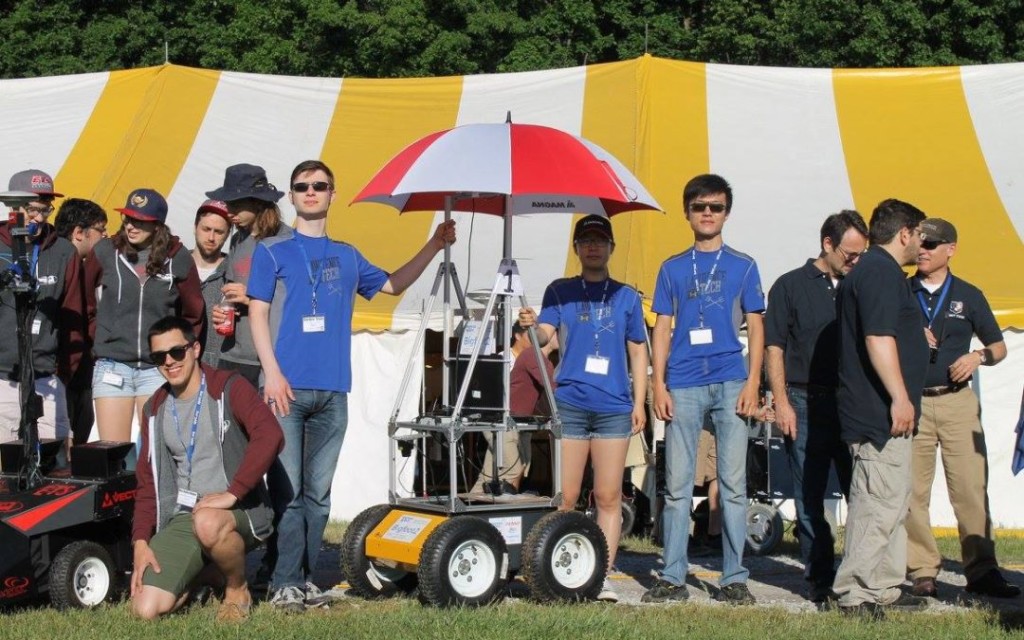
In late October, a video from MIT was making the rounds around at Clearpath. Since we usually have a lot of robots on hand and like doing interesting demos, we reached out to Shayegan to see if we could get some background information. He provided some insights into the challenges he faced when implementing this, and I was convinced that our team could pull a similar demo together so we could see how it worked in person.

Here’s what MIT’s setup looked like:

(Video: Melanie Gonick, MIT News. Additional footage and computer animations: Shayegan Omidshafiei)

At the most fundamental, this demo needs:

  • A small fleet of robots
  • A way for those robots to know where they are in the world
  • A computer to bring all of their information together and render a scene
  • A method of projecting the scene in a way which is aligned with the same world the robots use

In MIT’s case, they have a combination of iRobot Creates and quadrotors as their robot fleet, a VICON motion capture system for determining robot location, a Windows computer running ROS in a virtual machine as well as projector edge-blending software, and a set of 6 projectors for the lab.

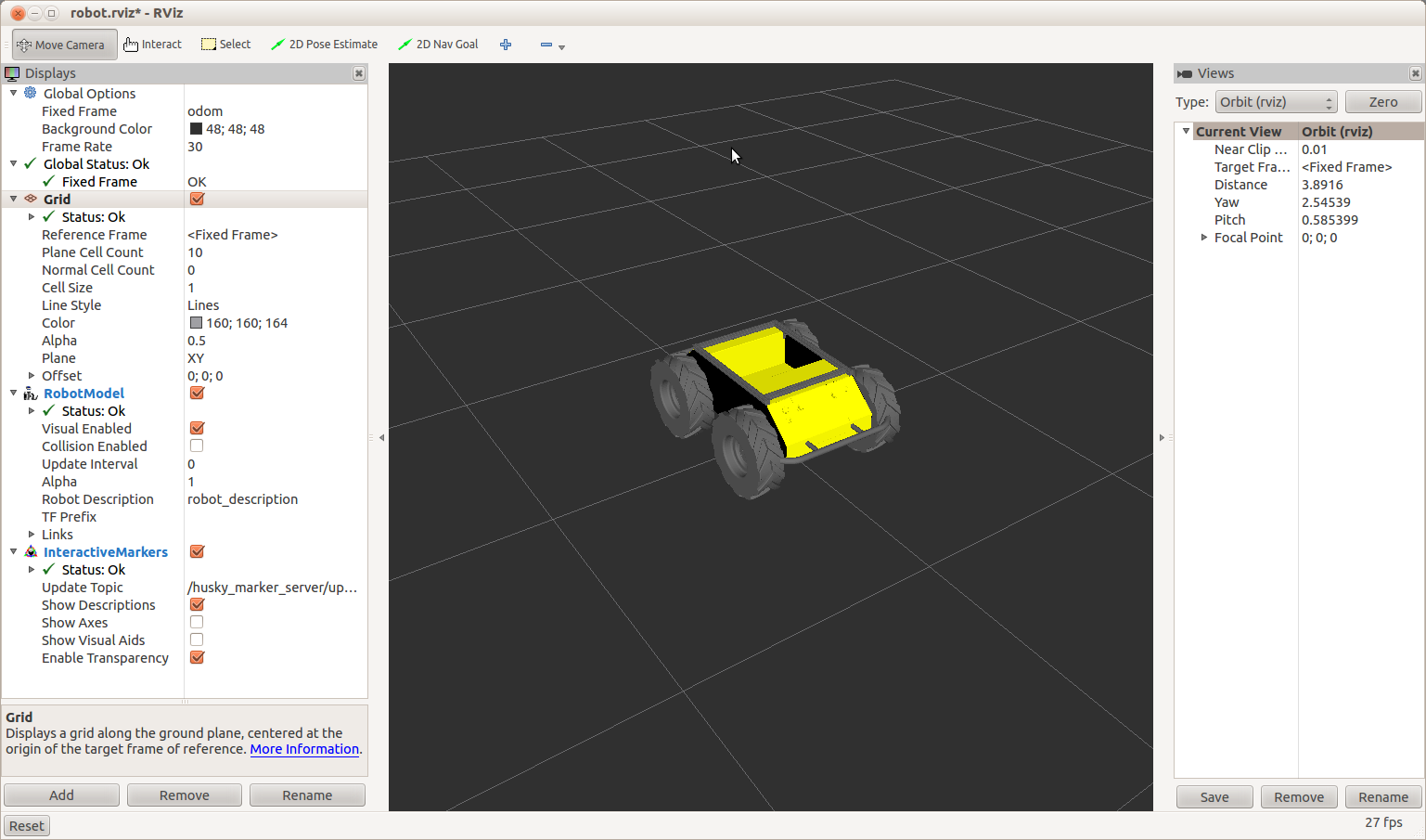
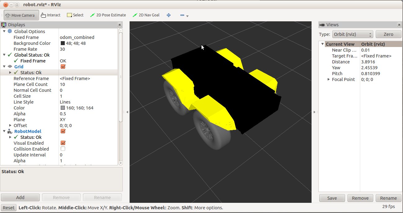
There were three things we wanted to improve on for our demo. First, we wanted to run all-ROS, and use RViz for visualizations. That removes the performance hit from running RViz in a VM, and also means that any visualization plugins we came up with could be used anywhere Clearpath uses ROS. Second, we wanted to avoid using the VICON system. Though we have a VICON system on hand in our lab and are big fans, we were already using it for some long-term navigation characterization at the time, so it wasn’t available to us. Finally, we wanted to make the demo more interactive.

Improvement #1: All-ROS, all the time!

To get this taken care of, we needed a way to either run edge-blending software on Linux, or to use projectors that did the edge blending themselves. Fortunately, something that might be a little known fact to our regular audience is that Christie is about 10 minutes away from Clearpath HQ and they make some of the best digital projectors in the world that, yes, do edge blending and more. A few emails back and forth, and they were in!

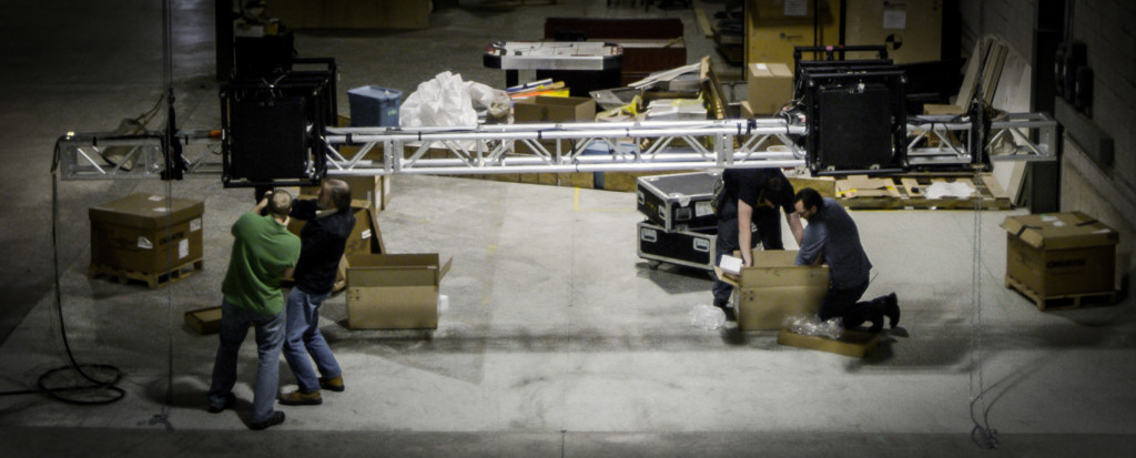
For this project, Christie arrived with four Christie HD14K-M 14,000 lumens DLP® projectors and two cameras. The projectors use Christie AutoCal™ software and have Christie Twist™ software embedded right in. Christie rigged the four projectors in a 2 x 2 configuration on the ceiling of our warehouse. The cameras captured what was happening on the floor and sent that information on the Christie AutoCal™ software, which then automatically aligned and blended the four projectors into one giant seamless 30 foot projection mapped digital campus.

Christie sets up the 3D Projection system. (Photo courtesy of Christie.)


Improvement #2: No motion capture

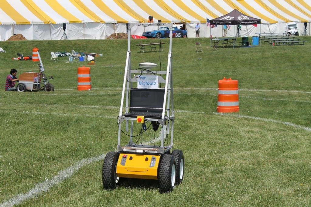
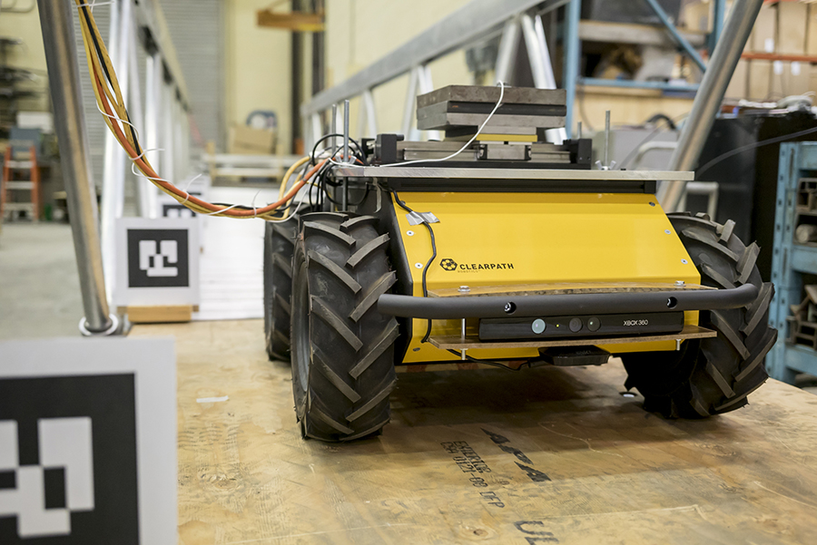
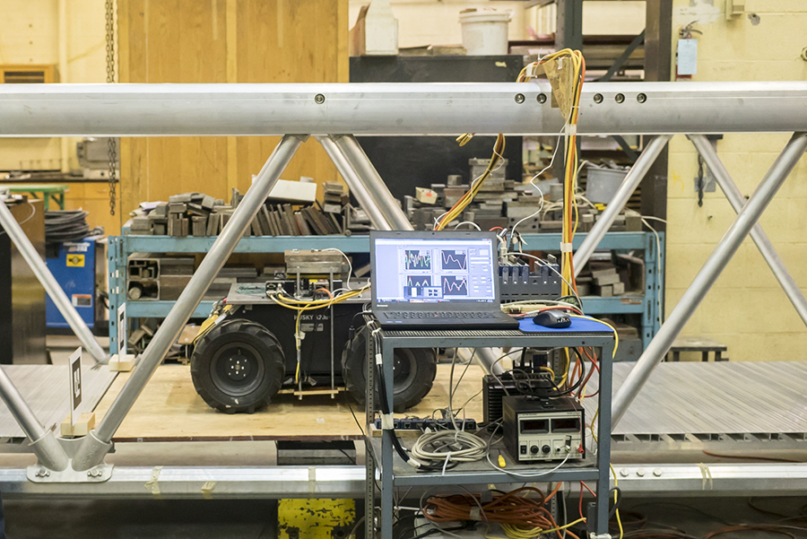
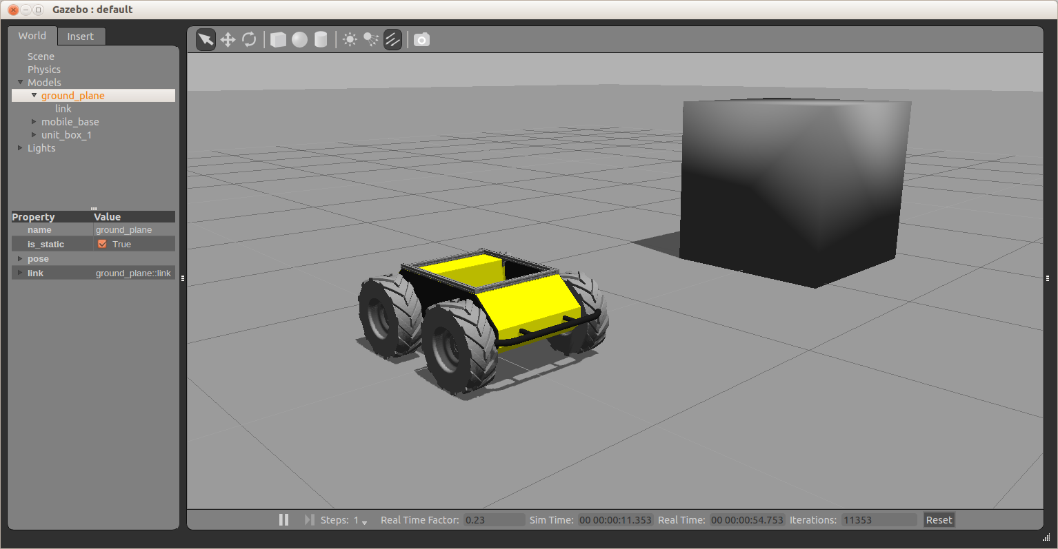
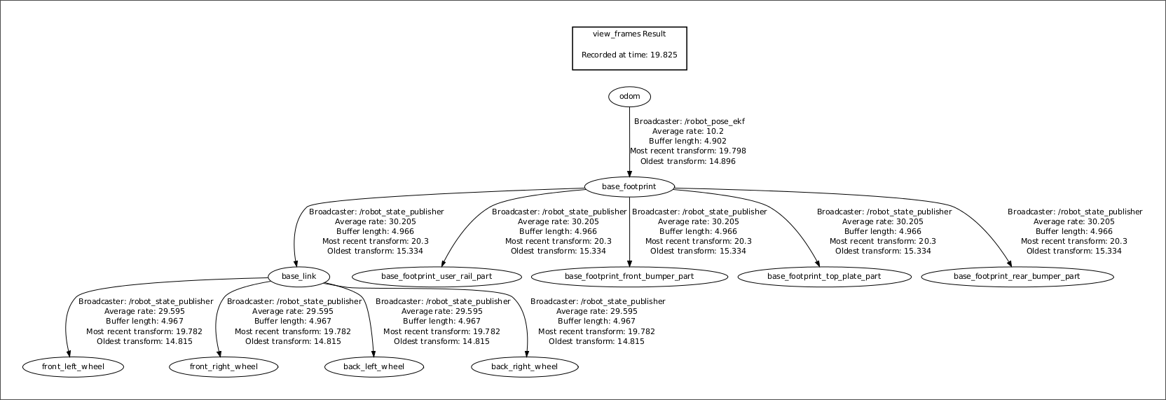
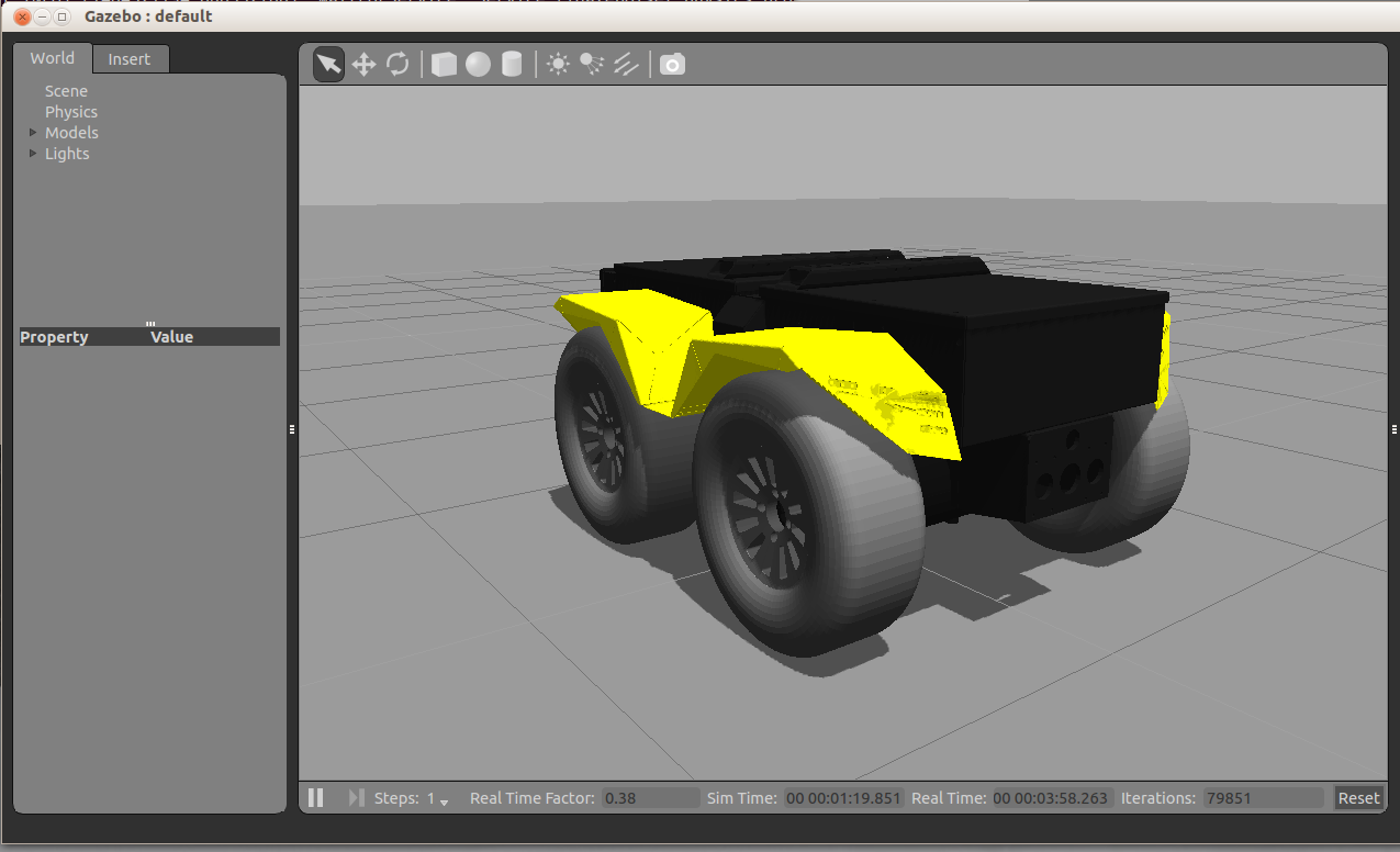
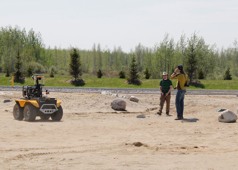
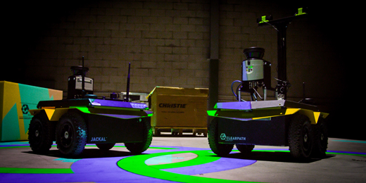
Getting rid of the motion capture system was even easier. We already have localization and mapping software for our robots and the Jackals we had on hand already had LIDARs mounted. It was a relatively simple matter to map out the world we’d operate in and share the map between the two robots.

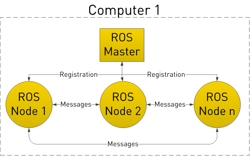
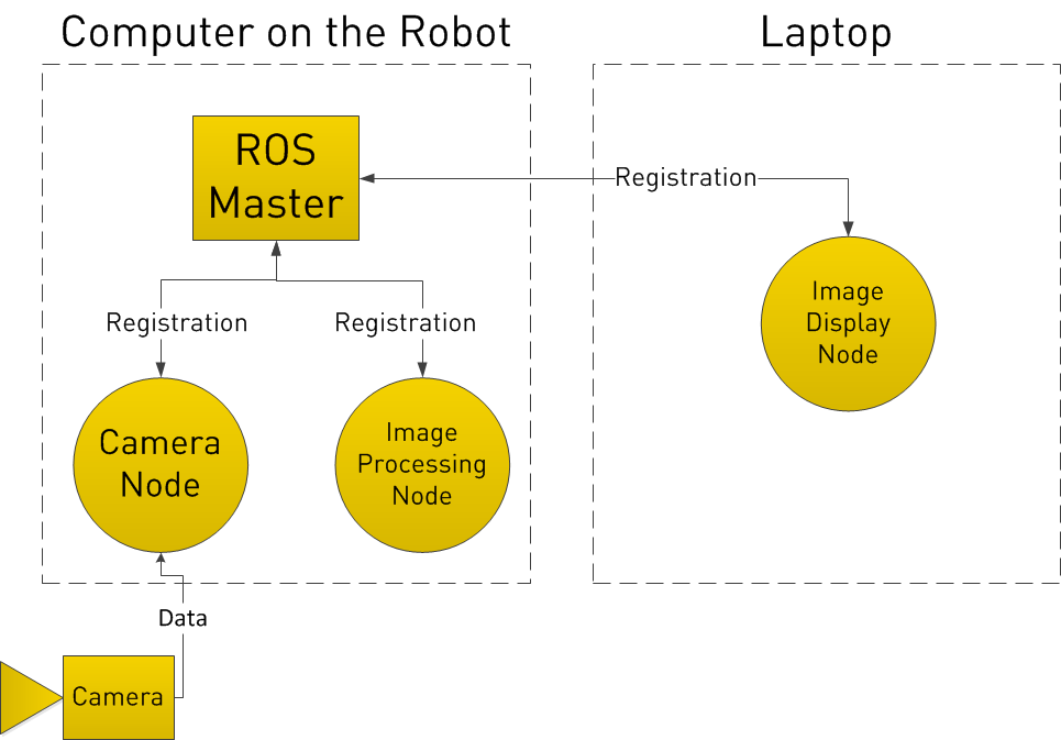
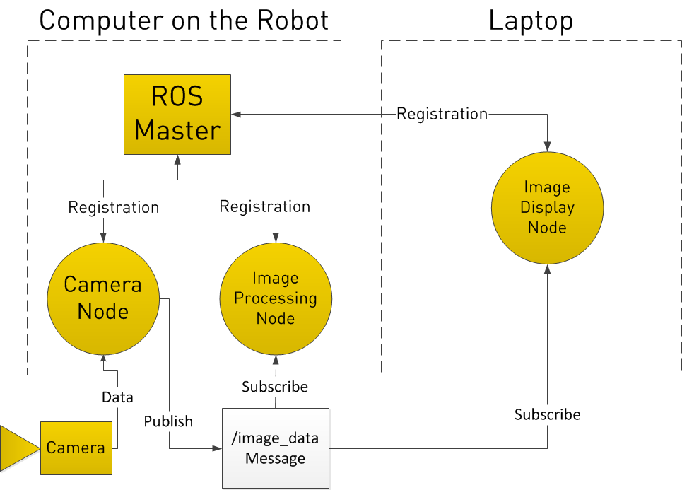
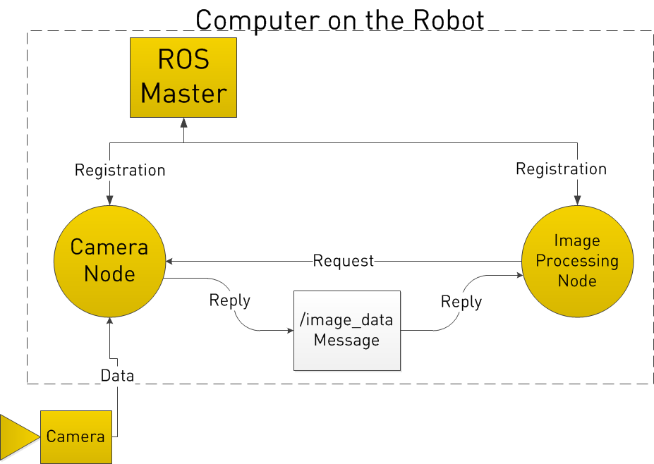
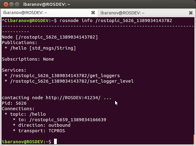
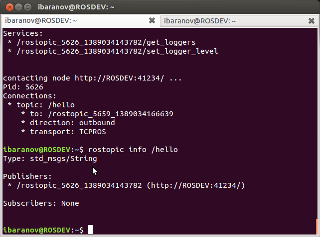
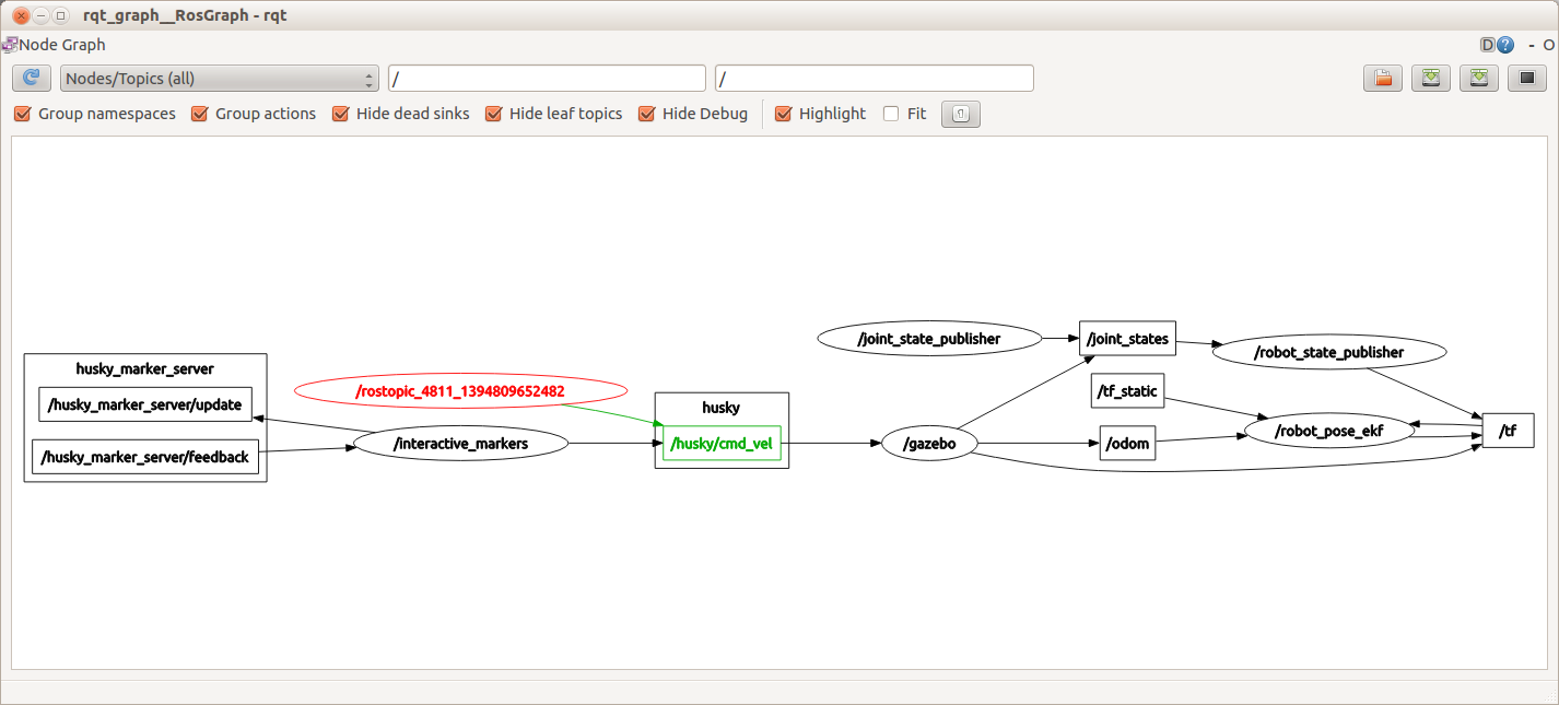
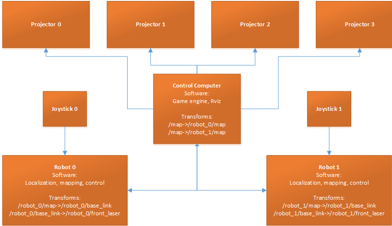
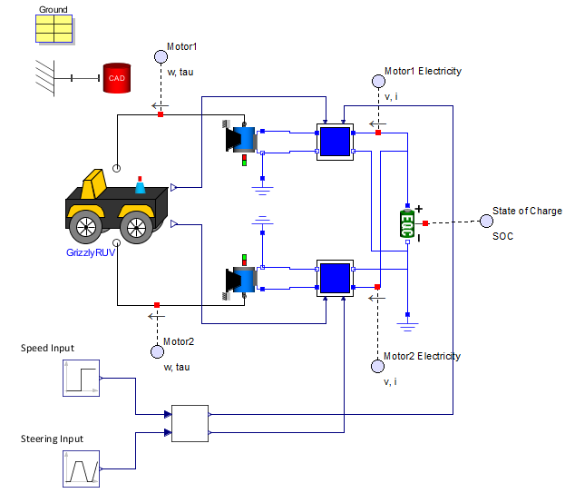
Now, I will make a slight aside here… Multi-robot operation in ROS is still not yet what one would call smooth. There are a few good solutions, but not one that is clearly “the one” to use. Since all of our work here had to fit into a week, we took the quick way out. We configured all of the robots to talk to a single ROS Master running on the computer connected to the computers, and used namespaces to ensure the data for each robot stayed tied to each robot. The resulting architecture was as follows:

Augmented-Reality-Blog-Diagram-1

All we had to do to sync the robot position and the projector position was to start training the map from a marked (0,0,0) point on the floor.

Improvement #3: More interactivity

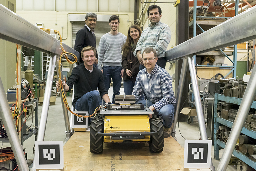
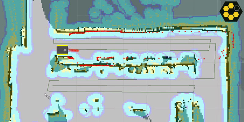
This was the fun part. We had two robots and everyone loves video games, so we wrote a new package that uses Python (via rospy), GDAL, and Shapely to create a real-life PvP game with our Jackals. Each Jackal was controlled by a person and had the usual features we all expect from video games – weapons, recharging shields, hitpoints, and sound effects. All of the data was rendered and projected in real-time along with our robots’ understanding of their environment.

And, as a final bonus, we used our existing path planning code to create a entire “AI” for the robots. Since the robots already know where they are and how to plan paths, this part was done in literally minutes.

The real question

How do I get one for myself?

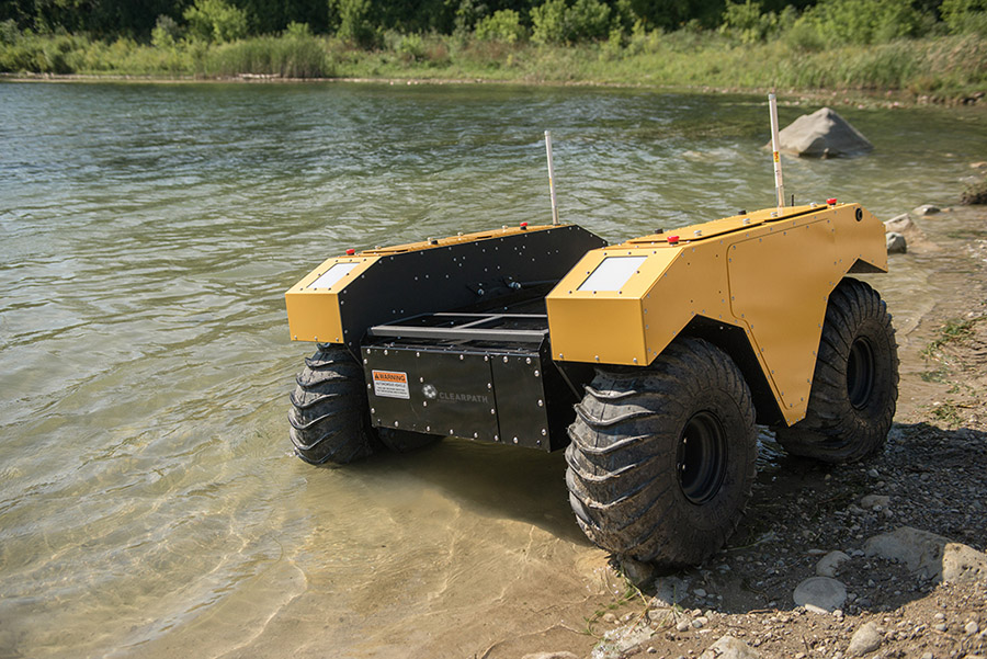
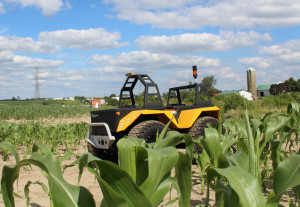
Robots: Obviously, we sell these. I’d personally like to see this redone with Grizzlies.

Projectors: I’m sure there are open-source options or other prosumer options similar to how MIT did it, but if you want it done really well, Christie will be happy to help.

Software: There is an experimental RViz branch here which enables four extra output windows from RViz.

The majority of the on-robot software is either standard with the Jackal or is slightly modified to accommodate the multi-robot situation (and can also be found at our Jackal github repository). We intend on contributing our RViz plugins back, but they too are a little messy. Fortunately, there’s a good general tutorial here on creating new plugins.

The game itself is very messy code, so we’re still keeping it hidden for now. Sorry (sad)
If you’re a large school or a research group, please get in touch directly and we’ll see how we can help.

Happy gaming!


Robots 101: Lasers

$
0
0

mapping
By Ilia Baranov

In this new Robots 101 series, we will be taking a look at how robots work, what makes designing them challenging, and how engineers at Clearpath Robotics tackle these problems. To successfully operate in the real world, robots need to be able to see obstacles around them, and locate themselves. Humans do this mostly through sight, whereas robots can use any number of sensors. Today we will be looking at lasers, and how they contribute to robotic systems.

the-day-the-earth-stood-still-gort3Overview

When you think of robots and lasers, the first image that comes to mind might come from science fiction; robots using laser weapons. However, almost all robots today use lasers for remote sensing. This means that the robot is able to tell, from a distance, some characteristics of an object. This can include size, reflective, color, etc. When the laser is used to measure distance in an arc around the robot, it is called LIDAR. LIDAR is a portmanteau of Light and Radar, essentially think of a sweeping radar beam shown in the films, using light.

Function and Concepts

By Mike1024, via Wikimedia Commons

All LIDAR units operate using this basic set of steps:

1. Laser light is emitted from the unit (usually infrared)
2. Laser light hits an object and is scattered
3. Some of the light makes it back to the emitter
4. The emitter measures the distance (more on how later)
5. Emitter turns, and process begins again

A great visual deception of that process to the right.

Types of LIDAR sensing

How exactly the laser sensor measures the distance to an object depends on how accurate the data needs to be. Three different methods commonly found on LIDAR sensors are:

Time of flight
The laser is emitted, and then received. The time difference is measured, and distance is simply (speed of light) x (time). This approach is very accurate, but also expensive due to the extremely high precision clocks needed on the sensor. Thus, it is usually only used on larger systems, and at longer ranges. Rare to use on robots


Phase difference

In this method, the emitted laser beam is modulated to a specific frequency. By comparing the phase shift of the returned signal on a few different frequencies, the distance is calculated. This is the most common way laser measurement is done. However, it tends to have limited range, and is less accurate than time of flight. Almost all of our robots use this.

Untitled-140x300Angle of incidence
The cheapest and easiest way to do laser range-finding is by angle of incidence. Essentially, by knowing what angle the reflected laser light hits the sensor, we can estimate the distance. However, this method tends to be of low quality. The Neato line of robotic vacuum cleaners use this technology.

Another thing to note is that so far, we have only discussed 2D LIDAR sensors. This means they are able to see a planar slice of the world around them, but not above or below. This has limitations, as the robot is then unable to see obstacles lower or higher than that 2d plane. To fix this issue, either multiple laser sensors can be used, or the laser sensor can be rotated or “nodded” up and down to take multiple scans. The first solution is what the Velodyne line of 3D LIDAR sensors employ, while the second solution tends to be a hack done by roboticists. The issue with nodding a LIDAR unit is a drastic reduction of refresh rate, from tens of Hz, down to 1 Hz or less.

Manufacturers and Uses

Some of the manufacturers we tend to use are SICK, Hokuyo, and Velodyne.
This is by no means an exhaustive list, just the ones we use most often.

SICK
Most of our LIDARs are made by SICK. Good combo of price, size, rugged build, and software support. Based in Germany

Hokuyo
Generally considered cheaper than SICK, in larger quantities. Some issues with fragility, and software support is not great. Based in Japan

Velodyne
Most expensive, used only when robot MUST see everything in the environment. Based in US.

Once the data is collected, it can be used for a variety of reasons. For robots, these tend to be:

  • Mapping
    • Use the laser data to find out dimensions and locations of obstacles and rooms. This allows the robot to find its position (localisation) and also report dimensions of objects. The title image of this article shows the Clearpath Robotics Jackal mapping a room.
  • Survey
    • Similar to mapping, however this tends to be outside. The robot collects long range data on geological formations, lakes, etc. This data can then be used to create accurate maps, or plan out mining operations.
  • Obstacle Avoidance
    • Once an area is mapped, the robot can navigate autonomously around it. However, obstacles that were not mapped (for example, squishy, movable humans) need to be avoided.
  • Safety Sensors
    • In cases where the robot is very fast or heavy, the sensors can be configured to automatically cut out motor power if the robot gets too close to people. Usually, this is a completely hardware-based feature.


Selection Criteria

A lot of criteria is used to select the best sensor for a given application. The saying goes that an engineer is someone who can do for $1 what any fool can do for $2. Selecting the right sensor for the job not only reduces cost, but also ensures that the robot has the most flexible and useful data collection system.

  • Range
    • How far can laser sensor see? This impacts how fast a robot is able to move, and how well it is able to plan.
  • Light Sensitivity
    • Can the laser work properly outdoors in full sunlight? Can it work with other lasers shining at it?
  • Angular Resolution
    • What is the resolution of the sensor? More angular resolution means more chances of seeing small objects.
  • Field of view
    • What is the field of view? A greater field of view provides more data.
  • Refresh rate
    • How long does it take the sensor to return to the same point? The faster the sensor is, the faster the robot can safely move.
  • Accuracy
    • How much noise is in the readings? How much does it change due to different materials?
  • Size
    • Physical dimensions, but also mounting hardware, connectors, etc
  • Cost
    • What fits the budget?
  • Communication
    • USB? Ethernet? Proprietary communication?
  • Power
    • What voltage and current is needed to make it work?
  • Mechanical (strength, IP rating)
    • Where is the sensor going to work? Outdoors? In a machine shop?
  • Safety
    • E-stops
    • regulation requirements
    • software vs. hardware safety

For example, here is a collected spec sheet of the SICK TIM551.

Range (m) 0.05 – 10 (8 with reflectivity below 10%)
Field of View (degrees) 270
Angular Resolution (degrees) 1
Scanning Speed (Hz) 15
Range Accuracy (mm) ±60
Spot Diameter (mm) 220 at 10m
Wavelength (nm) 850
Voltage (V) 10 – 28
Power (W) (nominal/max) 3
Weight (lb/kg) 0.55/0.25
Durability (poor) 1 – 5 (great) 4 (It is IP67, metal casing)
Output Interface Ethernet, USB (non-IP67)
Cost (USD) ~2,000
Light sensitivity This sensor can only be used indoors.
Other Can synchronize for multiple sensors.Connector mount rotates nicely.


If you liked this article, you may also be interested in:

See all the latest robotics news on Robohub, or sign up for our weekly newsletter.


AgBot Robotic Seeding Challenge powered by $50K grant for Grizzly RUV

$
0
0

agbot_seeding_challenge_2016_clearpath By Rachel Gould

The 2016 agBOT Robotic Seeding Challenge challenges participants to build unmanned robotic equipment to plant, measure and track multiple crop seeds to improve farming efficiency. The objective of the agBOT challenge is to reduce the harmful chemical by-products and erosion caused by inefficient farming techniques. The challenge will also inspire new solutions to reduce farms’ carbon footprints while increasing production – essential given that the agricultural sector must support the projected global population of nine billion by the year 2050. Clearpath Robotics, in conjunction with airBridge, is proud to offer a $50,000 grant toward the purchase of the Grizzly Robotic Utility Vehicle for teams in the 2016 challenge.

More about agBOT

The 2016 agBOT competition will be held on May 7, 2016. Additional challenges are set for 2017 and 2018. The 2016 competition will be hosted by Gerrish Farms in Rockville, Indiana, where competitors will be challenged to revolutionize the industry by improving precision and efficiency.

Feeding the world’s nine billion people

Although farming has become mechanized, the evolution of agricultural techniques to include unmanned robots provides a unique opportunity. The agricultural sector can increase productivity and sustainability by using intelligent robotics to analyze current farming practices including fertilization and seedling variety. This concept is paramount in the world of shrinking farming circles and an ever-growing population.

The bot to get it done!

Grizzly RUV seeding a field.

This year’s agBOT competition requires a robot that can function as an unmanned crop seeder; it must plant two types of seeds over half-mile-long rows. It must also supply real-time data using a mobile tracking antenna and a variety of analytics including down pressure and variety placement. Participating teams are responsible for developing all software, sensors and human-machine control interfaces to control tasks.

This complex list of requirements requires a flexible, rugged, high performing solution, which is why we’re excited to partner with airBridge to offer a $50,000 grant for Grizzlies that are used in the competition.

Clearpath_Grizzly_Agbot_Seeding_Challenge
Grizzly RUV in a corn field.

Grizzly is Clearpath’s largest all-terrain battery operated robot. The mobile research platform offers the performance of a mini-tractor and the precision of a robot with a max payload of 1320 lbs, max speed of 12 mph, 8 inches of ground clearance, and 5V, 12V, 24V and 48V user powers. See here for all technical specs.

Ready to participate in the agBOT 2016 challenge? Want to take advantage of this unique Grizzly grant opportunity? Get in touch with one of our unmanned experts.


If you liked this article, you may also be interested in:

See all the latest robotics news on Robohub, or sign up for our weekly newsletter.

Simulating in MapleSim

$
0
0

maplesimBy Ilia Baranov

Robots are expensive and they usually depend on batteries. What if you want to run an experiment with 100 robots, running for 10 hours? To help answer this question, ROS has built in support for robot simulation in the form of Gazebo. While this works quite well, it is currently unable to simulate physical properties like batteries, temperature, surface roughness. If your robotics research depends on accurate models, you may want to consider looking at MapleSim® 2015 – a high performance physical modeling and simulation tool developed by Maplesoft™.

Below we can see a video of the Grizzly RUV taking an open loop control path around a surface. Elements like current and voltage provided by the batteries, surface slipperiness and weight distribution all play a role in where the Grizzly actually ends up. To see what we’re referring to, watch the quick simulation video below:

The MapleSim model features a 200 Ah lead-acid battery pack with a nominal voltage of 48 V, similar to the Type B battery pack used in the robot, to provide electrical power to move the vehicle on an uneven terrain. The lead acid battery used in the model is part of MapleSim’s Battery Component Library. The physical behaviors of the battery are described by mathematical expressions curve-fitted based on experiment measurements to provide the accurate battery voltage and state of charge during the operations of the robot.

The interaction forces and moments at the tire-terrain contact points are generated based on a 3D tire model. A 3D mathematical expression is used to describe the terrain surface to allow the tire-terrain contact points to be calculated based on the position of the vehicle. This 3D function is also used to generate the STL graphics of the terrain for animation (see Figure 1).

The model also outputs electric motor torques, speeds, and battery state of charge as shown below:

Results_window-1024x619

Setting up the simulation involves using the Grizzly RUV MapleSim model, available at the bottom of this post. The graphical representation is easy to understand and also quick to modify.

unnamed


Maple and MapleSim provide a testing and analysis environment based on the virtual prototypes of the model. A number of analysis can be performed:

  • Virtual testing and analysis: an engineer can easily test the operations of the robot for any design in a virtual environment through simulations in MapleSim. Using Maple, different terrain surface conditions and tire force models to fit different test scenarios can be generated. As an example, the plot below shows different battery energy consumption (state of charge) rates under different terrain conditions.

graph

  • Battery optimization: the developed MapleSim model can be coupled with Maple’s powerful optimization toolboxes to determine the optimal battery size and optimize the Battery Management System (BMS) to minimize energy consumption, reduce battery temperature, and increase battery service life.
  • Motor sizing: the robot is equipped with four electric motors that are independently controlled to provide wheel torques and steering maneuvers. The seamless integration with Maple will allow the motor sizing optimization to be performed based on MapleSim simulations.
  • Chassis design and payload distribution: the virtual prototype of the system will allow engineers to easily vary payload locations and distributions and analyze their effects, e.g., roll-over, stability, controllability, etc., on certain tasks.
  • Path planning: Using Maple, different terrain surface conditions and tire force models to fit different test scenarios can be generated for path planning.
  • Model-based controller design: the MapleSim model will allow the control strategies to be designed and tested for accuracy before being deployed on a real vehicle.
  • Localization and mapping: the high-fidelity dynamic model of the robot will allow state estimation algorithms, such as Kalman filter and other Bayesian-based filtering algorithms, to be performed at a high accuracy.
  • Optimized code generation: optimized C code can be generated from the MapleSim model for purpose of implementations of control, localization, and path planning strategies.

See here for more information on simulating the Grizzly in MapleSim.


3 supply chain trends to watch for in 2016

$
0
0

factory_arm_robot_packing_manipulation
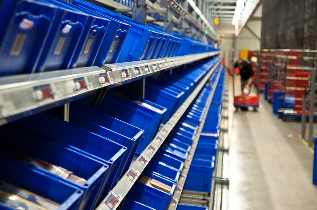
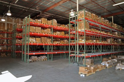
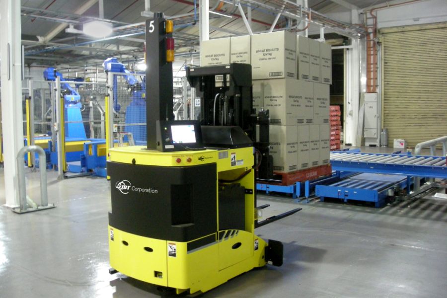
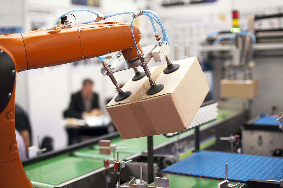
The New Year is upon us and with that comes predictions of what 2016 has in store. Will Automated Guided Vehicle (AGVs) continue to drive materials on the factory floor? What is ‘Industry 4.0’ and when will it take shape? The factory of the future is around the corner and these three supply chain trends for 2016 are the ones that will take us there.

1. Increased reliance on automation and robots

Industry Week reports that 2016 promises “vastly more automation for concentrating human effort on details and customization.” With warehouses experiencing increased cost pressures and supply chain complexities, operators are seeing just how much technology has advanced and how automation in particular can provide flexible transportation solutions. Solutions such as OTTO, for instance, offer infrastructure free navigation and virtually limitless flexibility for material transport in factories. With this level of automation, robots can be relied upon to complete simple yet important tasks such as material transport or line side delivery, while the human workforce will be able to focus efforts on complex tasks, problem solving and strategy.

2. Realization of the Industry 4.0 vision

Internet_of_Things_Smart_phone_IoT_conveyor_Belt_industry_factoryIn Gartner’s top 10 Strategic Technologies for 2016, analysts predict that the Internet of Things will have significant growth and impact over the next year in particular. Automation is only a piece of the puzzle when considering Industry 4.0; these evolutionary ‘smart factories’ will emerge with interconnected, centrally controlled solutions that are starting to be available to the marketplace. These solutions not only communicate with other material transport units (i.e.: the fleet) on the factory floor, they also communicate with people by providing perceptive light displays and integrating into the existing WMS to receive dispatched tasks. In an interview with Forbes, Rethink Robotics CPMO Jim Lawson summed things up quite nicely, “We’ll see an aggressive push by sector leaders to accelerate the realization of the Industry 4.0 vision. Specifically, big data analytics combined with advances in cloud-based robotics.”

3. Service chains will become more important than product chains

warehouse_forklift_people_work_supply_chain_management
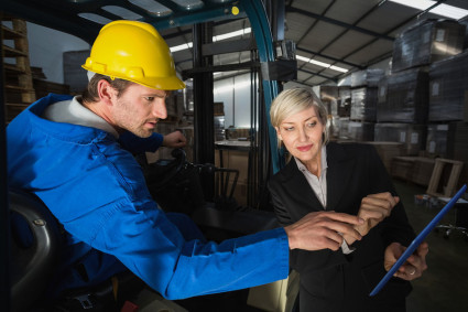
A supply chain is a system of organizations, people, activities, information, and resources that work together to move a product, whereas a production chain is the steps that needs to take place in order to transform raw materials into finished goods. The supply chain trend of service chains becoming more important than product chains is something that will develop over the next 10 years, although it’s already becoming reality. Providing great, reliable products is a standard expectation in the marketplace; whereas service is often perceived as a ‘nice-to-have’ within manufacturing. SupplyChain247 explains, “Increasingly, discerning consumers are demanding more from pre and post-sales service for the goods they buy.” We can apply this statement to technology suppliers as well – as Industry 4.0 takes form, and automation and robots become paramount, providers of those technologies must offer factory operators more than the technology itself. A full solution package will include hardware, software and service to offer ongoing support and true business relationships within the supply chain.


Interview: The team behind the apple harvesting robot

$
0
0

Source: Clearpath Robotics

By: Chris Bogdon
Amir Degani is an assistant professor at Technion Institute of Technology and Avi Kahnani is the CEO and Co-Founder of Israeli robotics start-up Fresh Fruits Robotics. Together, they are developing an apple harvesting robot that can autonomously navigate apple orchards and accurately pick fruit from the trees. I got the chance to sit down with Amir and Avi to learn more about the project. In our talk, they discussed the robot’s design, the challenges of apple picking, tree training and their experience demoing the robot for Microsoft’s CEO at the Think Next 2016 exhibition.

Tell me a little bit about CEAR Lab.

AD: I founded the CEAR Lab about four years ago after finishing my PhD and post doc at Carnegie Mellon University in Pittsburgh. I came back to the Technion in Israel and started the Civil, Environmental, Agricultural Robotics lab in the Faculty of Civil and Environmental Engineering. We work on soft robots, dynamic robots, and optimization of manipulators, mostly with civil applications, a lot of them related to agriculture. Other applications are search and rescue, automation in construction and environmental related work as well. But, generally, we’re mostly focused on agriculture robotics and robotic systems in the open field.

How did the apple harvesting robot project come to fruition?

AD: One of my PhD students is doing more theoretical work on task-based design of manipulators. Because cost is very important in agriculture, we’re trying to reduce price and find the optimal robot to do specific tasks. We’re actually seeing that different tasks, although they look very similar to us- apple picking or orange picking or peach picking – are actually very different if you look at the robot’s kinematics. We might need different joints, different lengths and so on. So we’re collecting data and modeling trees, we’re doing optimization and we’re finding the optimal robot for a specific task. This is something we have been working on for a few years. As part of this work, we are not only designing the optimal robot, but are also looking at designing the tree – finding the optimal tree in order to further simplify the robot.

There is a new Israeli start-up called FFRobotics (Fresh Fruit Robotics or FFR). Avi, who is the CEO and Co-Founder, approached us a few years ago after hearing one of my students give a talk on optimization of a tasked-based harvesting manipulator. FFR are building a simple robotic arm – a three degree of freedom Cartesian robot, with the goal of having 8 or 12 of these arms picking apples (or other fruits) simultaneously. We were helping them with the arm’s optimization. We started collaborating and then a few months ago, Microsoft approached us and asked us to exhibit at their Think Next exhibition that they have every year. So we decided to put one of the arms on our Grizzly RUV robot which fit pretty nicely. We brought those to the demo, along with a few Jackals and had a pretty good time!

Tell me a bit about how the robot works and its components.

AD: So the FFR arm has a vision system to segment and detect the apples. After it finds an apple, it gives the controller the XYZ location and the arm then reaches for the fruit. It has an underactuated gripper at the end with a single motor which grips the apple and rotates it about 90 degrees to detach it. The arm doesn’t go back to the home position, it just retracts a bit, lets go and the apples go into a container. In our lab, we are concentrating right now on the automation of the mobile robots themselves – on the Grizzly, Husky, and Jackals – we have a few of your robots. Fruit Fresh Robotics is working primarily on the design of the manipulator.

What kind of vision sensors are being used?

AD: On the Grizzly, we have an IMU, SICK LIDAR in Front, a stereo camera on a Pant-Tilt unit, and a dGPS. The arm uses a Kinect to do the sensing, but FFR is also looking into time of flight sensors to provide better robustness in the field.

Robot prepares to pick the next apple off the tree at Microsoft’s Think Next exhibition. Source: Clearpath Robotics

What would you say is the most challenging part of automating apple picking?

AD: I believe that the most difficult thing is making something cheap and robust. I think the best way is to not only think of the robot but also to train the trees to be simpler. Now this has been done in the past decade or two to simplify human harvesting. In extreme cases, you can see fruiting walls that are nearly planar. They did this to make it a bit simpler for human harvesters. This is even more important for robotic harvesting. Trying to get a robot to harvest apples on a totally natural tree is extremely complex, and you will most likely need a 6-7 degree of freedom robot to do it. In terms of vision, perception will be very difficult. People have tried it in the past and it just doesn’t make sense and makes everything too expensive for farmers to use.

By taking simpler trees, ones that were trained and pruned as the ones in our collaboration with Fresh Fruit Robotics, you can actually use a three degree of freedom robot – the simplest Cartesian robot – to do the picking. But, I think you can even go further to make the tree in a more optimal shape for a robot, let’s say a quarter of a circle. This may not be good for a human, but might be perfect for a robot and perhaps will allow us to use simpler robots that only need two degrees of freedom. So, making the system robust while keeping costs down is the hardest part and in order to do that you have to work on the tree as well.

How exactly do you train a tree?

AD: Training systems such as a fruiting-wall require high density planting while ensuring that the trunk and branches are not too thick. In order to do that you have to support them with a trellis and other engineered support system. You want to make them optimal so that all the energy and water goes mostly to the fruit and not the tree itself. This has been done for a while now, and we are essentially piggy backing on that. The simplification of trees may be even more important for robotics than for humans, if we want robots to go into fruit picking and harvesting.

Can the robots autonomously navigate and patrol the apple orchards?

AD: Not at the moment. We are in the process of doing it now on all of our robots. Right now we are trying to do full SLAM on an orchard in order to do patrolling for harvesting. This is the goal we are aiming for this summer.

How do you compensate for weather effects?

AD: In Israel the weather is relatively mild, so the problem is usually with sun and wind rather than snow and rain. The main problem the weather creates is with the perception of the robot, having to compensate for changes in light and in position of the objects. To overcome this FFR uses a cover, like a tent, to shield the tree and the robot. If it’s windy, you have to use fast closed-loop control because if the target starts moving after it’s been perceived, the system has to keep on tracking it in order for the gripper to accurately grip the object where it is and not where it was 10 seconds ago.

Why did you choose the Grizzly RUV for this project?

AD: We’ve had the Husky UGV for a while. We also have some older robots from 10 years ago, such as a tractor that we modified to be semi-autonomous. But, none of these vehicles were strong enough to actually do real work while being easily controllable. We wanted to carry bins full of fruit which weigh more than half a ton and we didn’t have a robot that could do that. Also, I wanted to have something that my students could take and apply the algorithms to a real-sized robot that could work in the field. We started with a TurtleBot to learn ROS, and then moved to the Husky. Then I wanted something I could just scale up and actually move to the field. That’s what we’re doing right now. It’s pretty new, so we’re in the early stages of working with it.

How did you find the integration process?

AD: Mechanical integration was very easy. We have not yet fully completed the electrical integration – instead we have two separate controllers and two separate electrical systems. Later on it will be relatively easy for the electrical system to be plugged into the robot since it uses the same voltage more or less. But right now it is decoupled.

Are you at a point where you can quantify the efficiency and cost benefits of the robots compared manual picking?

AK: We designed the system to pick approximately 10,000 high quality fruits per hour – that is without damaging the fruit while picking. Assuming working during the day only, the robot could potentially save farmers 25% in harvesting costs. It is important to understand that the same system will be able to pick other fresh fruits by replacing the end effector (gripper) and the software module. This option to harvest multiple fruits types increases the efficiency of the system dramatically.

What was it like to demo the robot to Satya Nadella, CEO of Microsoft, at the Think Next conference?

AD: It was exciting! He didn’t have a lot of time to spend at our booth. But it was an exciting exhibition with many demonstrators. We had the biggest robot for sure. It was fun! The FFR arm picked apples from the tree, and dropped them in the Jackal. Then, we drove the Jackal around delivering picked apples to people and they liked it. For safety reasons, we didn’t move the Grizzly. We just parked it and it didn’t move a centimeter the whole time. It was fun bringing such a big robot to the demo.

Picked apples were placed in a basket on top of a Jackal UGV and delivered to people in the crowd at Microsoft’s Think Next exhibition. Source: Clearpath Robotics

How close are you to a commercial release?

AK: Following last year’s field tests we believe the commercial system is about two years ahead. During the summer of 2016 we plan to test a full integrated system in the apple orchard, picking fruits from the trees all the way to the fruit bin. The first commercial system will be available for the 2017 apple picking season.

What is next for CEAR lab?

AD: We will continue working on the theoretical part of the optimization of the robotic arms. We’re looking into new ideas on re-configurability of arms – having arms doing different tasks and pretty easily switching from one task to another. With the Grizzly, we’re working on autonomous navigation of the apple orchards and are also working on a non-agricultural project related to search and rescue. We designed a suspension system on the Grizzly and mounted a stretcher on top of it. The motivation is to be able to evacuate wounded from harm’s way autonomously in rough terrain.

We are pretty happy with our robots. It’s a big family! We pretty much have all of Clearpath’s robots. Technical support is great and it’s been fun!

The post Interview: The Team Behind The Apple Harvesting Robot appeared first on Clearpath Robotics.

5 innovation challenges in materials transport

$
0
0

warehouse-distribution-centre-supply-chain

by: Meghan Hennessey

Walk into any manufacturing facility today. Forklifts and AGVs may be in operation serving specific parts of the manufacturing floor, but you’ll also see hundreds of people at work— pulling, tugging, and pushing goods from point A to point B. Why is it that we are still using humans — our most important asset — for materials transport? Yet, despite being the grease for the manufacturing wheel, materials transport remains an untapped opportunity for automation and innovation in most manufacturing establishments.

To continue to prosper and grow, manufacturers need to embrace innovation to overcome some of the significant challenges they face in the day-to-day operation of their business. Here are some of the challenges manufacturers are battling today:

Challenge #1: Adapting to a new velocity of change
From cola’s to custom cars, consumers are now demanding more variety in the goods they purchase. This insatiable appetite for choice is putting new pressure on industry to manufacture goods in a different way. To deal with the explosion of SKUs customers want available on store shelves, manufacturing environments need to be far more flexible than they’ve been in the past. To get there, manufacturers are turning to dynamic manufacturing methods such as mixed-model assembly lines (MMALs) and/or just-in-time (JIT) kit-based delivery to produce smaller batch runs with a greater variety and variation of products.

Challenge #2: Managing rising complexity

SKU proliferation is caused when consumers demand endless variations of a similar product. Source: usdagov/Flickr

Customers may demand that manufacturers produce a greater variety of product with a higher velocity, but these flexibility demands are creating chaos on the factory floor. As traditional automation and material handling systems are typically built into the infrastructure and cannot be easily or cost-effectively adapted to deal with ongoing change, manufacturers are continually struggling to contend with increasing complexity in the way products are built, the way raw materials are transported, and the way people and machines move through the facility.

Challenge #3: Remaining competitive on a global playing field
While North American manufacturers continue to wrestle with the complexities created by dynamic manufacturing models, there is yet another large dynamic at play: offshore competition. Manufacturers working in offshore locations such as China, Mexico, Eastern Europe and Africa are able to capitalize on lower local labor costs to produce goods and services for the market more affordably, making them significantly more competitive than their US counterparts. North American factory owners face higher real estate prices, higher labor costs, and more stringent environmental and regulatory compliance requirements than their offshore counterparts. Therefore, in order to be competitive in this global marketplace, a North American industrial center must find ways to be more efficient than its low cost country counterparts. Automation plays a significant role in helping North American manufacturers achieve operational parity; companies can optimize distribution, logistics, and production networks by using powerful data-processing and analysis capabilities.

Challenge #4: Reducing operating costs
In order to successfully compete against offshore rivals, US manufacturers need to reset the bar for production density and re-shore their operations. Automation is the linchpin within this strategy. As more manufacturers introduce automation, including robotics on the factory floor, production efficiency will rise, cost will fall, and the manufacturer will gain greater competitive advantage.

Challenge #5: Inefficient and chaotic materials transportation

Source: Flickr, creative commons

The variety and velocity at which goods must be produced, the increasing level of complexity this creates for manufacturers, and the ongoing cost pressures faced by North American industry become an acutely obvious problem when one looks at the way materials are transported and flow through a manufacturing facility. Three key elements tied to materials movement, transport (moving products that are not actually required to perform the processing), motion (people or equipment moving or walking more than is required to perform the processing) and waiting (for the next production step, interruptions of production during shift change) are among the original seven wastes of LEAN.

The post 5 Innovation Challenges in Materials Transport appeared first on Clearpath Robotics.

4 reasons why Industry 4.0 will leave AGVs behind

$
0
0
ATV in warehouse. Source: Wikipedia Commons
AGV in warehouse. Source: Wikipedia Commons

By Paula de Villavicencio

Technology has been in development for the last decade and has now come to fruition in the form of self-driving vehicles. These vehicles are driving into industrial centers and beginning to replace traditional AGVs, and it’s no wonder why. The first AGV was introduced in the early 1950s and more than 50 years later it has marginally advanced from following radio transmissions from the ceiling to following magnetic tape on the floor. Its slow advancement isn’t the only limitation; AGVS are fixed, reactive, captured and adoptive machines, and they leave a lot to be desired in today’s complex manufacturing environment.

AGV_BlogPost

1. Fixed not flexible
Like trains on their tracks, AGVs are fixed to a certain pathway and are unable to move off of it. These are not flexible machines, and while repeatable point-to-point navigation tasks are possible, many companies have fork trucks and manually driven tug vehicles working alongside the AGVs. Dynamic pathways are a necessary evolution in Industry 4.0, especially for innovating manufacturers with complex production systems.

2. Reactive not proactive
Yet, unlike trains, AGVs cannot move onto a new track direction to avoid collision or change their direction. In fact, if an AGV breaks down while on a preprogrammed pathway, all AGVs following the same pathway cannot move around it, and are unable to deliver or pick up their loads. This loss in movement can cost a company a great deal of money in a short amount of time.

3. Captured not collaborative
These machines are also unable to collaborate amongst each other to share the work in the most efficient way possible. Those AGVs that are preprogrammed to a specific pathway cannot move to a different path rapidly or easily to perform a different job. They are held captive in their preprogrammed task regardless of efficiency or changing manufacturing needs.

4. Adoptive not adaptive
Since the preprogrammed pathways have to be simple and unobstructed for the AGVs, many facilities pre-plan their layouts with the machines in mind. Transport aisles are designed for isolated AGV paths, and work areas are laid out to accommodate the vehicles’ planned route. When it comes to AGVs, manufacturers have to adapt to the machines, instead of the AGVs incorporating into an already existing facility. In some cases, factories and warehouses resort to manual transport methods instead of adopting AGV technology and all the prerequisite planning that it requires.

By advancing material transport for Industry 4.0 capabilities, we will see more technologies take the factory floor. Self-driving vehicles can offer flexibility, proactive planning, collaboration, and adaptive behaviours.


Interview: International Ground Vehicle Ground Competition (IGVC) winner on “Bigfoot 2” Husky UGV

$
0
0
Photo credit: Lawrence Tech University IGVC Facebook

By: Chris Bogdon

The International Ground Vehicle Ground Competition (IGVC) is an annual event that brings together teams of college students from all over the globe to compete in an autonomous ground vehicle competition. Teams are tasked to design and construct a fully autonomous unmanned robotic vehicle that can navigate around a challenging outdoor obstacle course under a prescribed time. This year’s IGVC went down in June at Oakland University, and while the competition was stiff, only one team could come out on top. That team was Lawrence Teach University (LTU), whose robot, Bigfoot 2, was built using the Husky UGV robotic platform.

We had a chance to sit down for a quick Q&A with team captain, Gordon Stein, to learn more about the design of the robot, challenges and key lessons learned by taking part in the competition.

Q: Tell us a bit about the design of Bigfoot 2?

A: Bigfoot 2 uses the Clearpath Husky platform, with our own frame and electronics placed on top of it. For sensors, we have a 2D LIDAR, a camera, a GPS, and a compass. The computer we used was one of the laptops our school provides to students. This meant we could easily get a replacement if needed. Our software is made in C#, which makes it easier for students in the robotics programming course to join the team.

We modified the platform to have larger tires with a smoother tread. The original tires had too much traction, and we were afraid that we would get disqualified from them ripping up the turf at the competition. In addition, it makes it easier for the robot to turn in place, and made the robot able to go slightly faster.

Photo credit: Lawrence Tech University IGVC Facebook

Q: Why did you choose the Husky UGV as your mobile base over other mobile platforms or creating your own?

A: Our team’s philosophy was to use as many “off-the-shelf” components as possible. We represent the Computer Science department, so we wanted to spend as much time as possible on our programming. Using an existing platform allowed us to have a working robot earlier in the year, so we could start programming instead of waiting for the chassis to be assembled.

Q: What was the most challenging part of preparing for the competition?

A: The most challenging part is testing. Our team has a simulator we made in a previous year, and we had set up a practice course on campus, but we still couldn’t prepare for everything at the competition. This is especially difficult because we don’t know the obstacles ahead of time. In the previous year, we didn’t prepare for ramps and a ramp stopped us. This year, we tested to make sure it could go over ramps and no ramps were at the competition. The advanced course always has obstacles that none of the teams are ready for, and that’s part of the challenge.

Q: What aspect of the design were you most and least worried going into the competition?

A: We were most worried about waterproofing. Our team tradition for the past few years had been to just attach an umbrella to the robot, but this doesn’t win us any points with the judges, and it doesn’t let us run in serious rain. The Husky chassis is water resistant, but the electronics we had on top of it is not. We purchased some vinyl material to use for waterproofing, but we weren’t able to make it into a real cover in time.

We were least worried about the new tires. We tested them to make sure they would work on slopes and ramps, and they definitely improved the steering.

Photo credit: Lawrence Tech University IGVC Facebook

Q: What were the key lessons learned by participating in the IGVC competition?

A: The key lesson we learned was to keep things simple. Some of the teams had very elaborate sensors and relied on dozens of ROS packages for their code, and many of them seemed to be having issues at the competition. While a 3D LIDAR would’ve opened up some new possibilities, we only needed a 2D LIDAR to see the barrels.

Q: What advice would you give to teams participating in next year’s challenge?

A: Our advice would be to spend time trying new ideas. We had one team member whose job was to try new ways to automatically adjust our camera to changing lighting conditions. None of them ended up being used at the competition, but it still allowed us to see what possible other solutions there could be.

See Bigfoot 2 in action

Watch Bigfoot 2 navigate the Auto-Nav Challenge Advanced Course

The post Interview: IGVC Winner on “Bigfoot 2” Husky UGV appeared first on Clearpath Robotics.

Clearpath Robotics launches “Warthog UGV”, the amphibious robot

$
0
0

warthog-UGV

Clearpath Robotics, a leading provider of mobile robotic platforms for research and development, has partnered with ARGO XTR to release Warthog – a large, amphibious, all-terrain mobile robot designed for application development. Warthog enables researchers to reliably test, validate, and advance their robotics research faster than ever before in real-world conditions, whether on land or in water.

“ARGO XTR (Xtreme Terrain Robotics) has a terrific record of manufacturing rock-solid outdoor platforms,” says Julian Ware, General Manager for Research Solutions at Clearpath Robotics. “Combined with our expertise in robotics, we’ve developed rugged platform suitable for a wide range of robotics applications in mining, agriculture, forestry, space, and environmental monitoring.”

Warthog’s light-weight aluminum chassis, low ground pressure, passive suspension system, and 24” traction tires allow it to easily traverse a variety of tough terrains including soft soils, thick muds and steep grades, all while carrying up to 272 kg of payload.    With built-in bilge pumps and an IP rating of 67, Warthog is fully weather-proof and amphibious, capable of moving through deep waterways at up to 4 km/h, or travel at speeds of up to 18 km/h while on land. The all-electric, skid steer platform has expandable power allowing for a runtime of 6 hrs and can be outfitted with quad tracks for ultimate traction and maneuverability in snow and sand.

“ARGO XTR is excited to partner with a progressive robotics company like Clearpath with our platform,” says Jason Scheib, ARGO XTR Robotics Program Director.  “The combination of our proven experience in amphibious and extreme terrain environments with our platforms with the progressive software and sensor integration from Clearpath Robotics, has created a second to none solution for a myriad of research and commercial applications.”

Designed for end-to-end integration and customization, Warthog includes an internal computer, IMU, wheel encoders, and mounting racks, as well as accessible user power and communication ports for integrating sensors, manipulators, and other third-party hardware.   Warthog is shipped with the Robot Operating System (ROS) preconfigured and a Gazebo simulation model, allowing researchers to get started quickly with existing research and widely available open-source ROS libraries.

Click here for more information.

If you liked this article, you may also be interested in:

See all the latest robotics news on Robohub, or sign up for our weekly newsletter.

Customer story: Deployable, autonomous vibration control of bridges using Husky UGV

$
0
0
Image: Clearpath
Image: Clearpath

Sriram Narasimhan’s research team are shaking things up in the Civil Engineering Structures Lab at the University of Waterloo. The research, which is led by Ph.D Candidate Kevin Goorts, is developing a new mobile damping system for suppressing unwanted vibrations in lightweight, flexible bridges. Whereas damping systems are often permanent fixtures built into the bridge, their system is designed to be adaptable, autonomous, and better suited for rapid, temporary deployment.

A SHIFT TOWARDS FLEXIBLE, LIGHT-WEIGHT STRUCTURES

Their work follows a recent industry shift towards using lightweight materials in the construction of civil engineering structures. Driven primarily by cost savings, as well as both the ease and speed of deployment, these lightweight structures could be a pedestrian bridge or a temporary bridge used in disaster relief scenarios, and are often more sensitive to external forces due to the reduced self-weight, and therefore require auxiliary damping devices.

Husky-based mobile bridge damping system on a full-scale aluminum pedestrian bridge. Image: Clearpath

HUSKY UGV: THE IDEAL MOBILE ROBOTIC PLATFORM

At the center of the team’s mobile control system is a Husky unmanned ground vehicle (UGV). An electromechanical mass damper mounted on top of the Husky is used to generate inertial control forces which are magnified by the body dynamics of the Husky. When situated on a bridge, the system is able to respond to changes in the structural response by autonomously positioning itself at the appropriate location and applying the desired control force.

For Goorts’ research, Husky UGV was the ideal mobile base upon which to develop their system. “The Husky is a rugged vehicle suitable for outdoor applications with sufficient payload capacity for both the damper and associated computational equipment.” said Goorts. “The low-profile and large lug thread tires are well suited for providing the necessary static friction to prevent sliding and transfer control forces. Moreover, Husky’s readily available ROS (Robot Operating System) integration allowed us to use several sensor types and position control algorithms.”

Linear motor and front-facing Kinect vision sensor mounted on Husky UGV mobile base. Image: Clearpath

The Husky is also equipped with a laptop running ROS and Kinect vision sensors on the front and back of the vehicle. Using wheel encoder data and measurements from the Kinect sensors, the system is able to perform SLAM (Simultaneous Localization and Mapping) and autonomously navigate back and forth along the span of the bridge. One of the immediate challenges the team faced was getting the robot to accurately localize on a bridge with a repetitive structural design – everything looked the same to the robot from different positions. To overcome this, they placed unique AR (augmented reality) tags along the bridge between which the robot could navigate.

A National Instruments (NI) cRIO is being used for all data processing tasks and execution of the structural control loops, and a TCP data link communicates between the ROS laptop and cRIO. Image: Clearpath.

BRIDGE VIBRATIONS REDUCED BY 70%

The effectiveness of the control system is tested using real-time hybrid simulation (RTHS), a dynamic testing method that couples the physical control system with a numerical model of the structure. These tests were carried out on a full-scale aluminum pedestrian bridge with re-designed panels to measure the forces being applied by the system. Results from the simulations show the system can provide up to a 70% reduction in the lateral displacement of the bridge.

The current prototype is suitable for bridges with a mass up to 1-tonne and is scalable to accommodate larger structures, either with a larger vehicle or with multiple vehicles that work cooperatively. Looking forward, the team is exploring the idea of making the system vehicle agnostic, which could allow any vehicle to be turned into an autonomous bridge stabilizing machine.

The post Customer Story: Deployable, Autonomous Vibration Control of Bridges Using Husky UGV appeared first on Clearpath Robotics.

If you liked this article, you may also be interested in:

See all the latest robotics news on Robohub, or sign up for our weekly newsletter.

Rapid outdoor/indoor 3D mapping with a Husky UGV

$
0
0

by Nicholas Charron

The need for fast, accurate 3D mapping solutions has quickly become a reality for many industries wanting to adopt new technologies in AI and automation. New applications requiring these 3D mapping platforms include surveillance, mining, automated measurement & inspection, construction management & decommissioning, and photo-realistic rendering. Here at Clearpath Robotics, we decided to team up with Mandala Robotics to show how easily you can implement 3D mapping on a Clearpath robot.

3D Mapping Overview

3D mapping on a mobile robot requires Simultaneous Localization and Mapping (SLAM), for which there are many different solutions available. Localization can be achieved by fusing many different types of pose estimates. Pose estimation can be done using combinations of GPS measurements, wheel encoders, inertial measurement units, 2D or 3D scan registration, optical flow, visual feature tracking and others techniques. Mapping can be done simultaneously using the lidars and cameras that are used for scan registration and for visual position tracking, respectively. This allows a mobile robot to track its position while creating a map of the environment. Choosing which SLAM solution to use is highly dependent on the application and the environment to be mapped. Although many 3D SLAM software packages exist and cannot all be discussed here, there are few 3D mapping hardware platforms that offer full end-to-end 3D reconstruction on a mobile platform.

Existing 3D Mapping Platforms

We will briefly highlight some more popular alternatives of commercialized 3D mapping platforms that have one or many lidars, and in some cases optical cameras, for point cloud data collection. It is important to note that there are two ways to collect a 3D point cloud using lidars:

1. Use a 3D lidar which consists of one device with multiple stacked horizontally laser beams
2. Tilt or rotate a 2D lidar to get 3D coverage

Tilting of a 2D lidar typically refers to back-and-forth rotating of the lidar about its horizontal plane, while rotating usually refers to continuous 360 degree rotation of a vertically or horizontally mounted lidar.

Example 3D Mapping Platforms: 1. MultiSense SL (Left) by Carnegie Robotics, 2. 3DLS-K (Middle) by Fraunhofer IAIS Institute, 3. Cartographer Backpack (Right) by Google.

1. MultiSense SL

The MultiSense SL was developed by Carnegie Robotics and provides a compact and lightweight 3D data collection unit for researchers. The unit has a tilting Hokuyo 2D lidar, a stereo camera, LED lights, and is pre-calibrated for the user. This allows for the generation of coloured point clouds. This platform comes with a full software development kit (SDK), open source ROS software, and is the sensor of choice for the DARPA Robotics Challenge for humanoid robots.

2. 3DLS-K

The 3DLS-K is a dual-tilting unit made by Fraunhofer IAIS Institute with the option of using SICK LMS-200 or LMS-291 lidars. Fraunhofer IAIS also offers other configurations with continuously rotating 2D SICK or Hokuyo lidars. These systems allow for the collection of non-coloured point clouds. With the purchase of these units, a full application program interface (API) is available for configuring the system and collecting data.

3. Cartographer Backpack

The Cartographer Backpack is a mapping unit with two static Hokuyo lidars (one horizontal and one vertical) and an on-board computer. Google released cartographer software as an open source library for performing 3D mapping with multiple possible sensor configurations. The Cartographer Backpack is an example of a possible configuration to map with this software. Cartographer allows for integration of multiple 2D lidars, 3D lidars, IMU and cameras, and is also fully supported in ROS. Datasets are also publicly available for those who want to see mapping results in ROS.

Mandala Mapping – System Overview

Thanks to the team at Mandala Robotics, we got our hands on one of their 3D mapping units to try some mapping on our own. This unit consists of a mount for a rotating vertical lidar, a fixed horizontal lidar, as well as an onboard computer with an Nvidia GeForce GTX 1050 Ti GPU. The horizontal lidar allows for the implementation of 2D scan registration as well as 2D mapping and obstacle avoidance. The vertical rotating lidar is used for acquiring the 3D point cloud data. In our implementation, real-time SLAM was performed solely using 3D scan registration (more on this later) specifically programmed for full utilization of the onboard GPU. The software used to implement this mapping can be found on the mandala-mapping github repository.

Scan registration is the process of combining (or stitching) together two subsequent point clouds (either in 2D or 3D) to estimate the change in pose between the scans. This results in motion estimates to be used in SLAM and also allows a new point cloud to be added to an existing in order to build a map. This process is achieved by running iterative closest point (ICP) between the two subsequent scans. ICP performs a closest neighbour search to match all points from the reference scan to a point on the new scan. Subsequently, optimization is performed to find rotation and translation matrices that minimise the distance between the closest neighbours. By iterating this process, the result converges to the true rotation and translation that the robot underwent between the two scans. This is the process that was used for 3D mapping in the following demo.

Mandala Robotics has also released additional examples of GPU computing tasks useful for robotics and SLAM. These examples can be found here.

Mandala Mapping Results

The following video shows some of our results from mapping areas within the Clearpath office, lab and parking lot. The datasets collected for this video can be downloaded here.

The Mandala Mapping software was very easy to get up and running for someone with basic knowledge in ROS. There is one launch file which runs the Husky base software as well as the 3D mapping. Initiating each scan can be done by sending a simple scan request message to the mapping node, or by pressing one button on the joystick used to drive the Husky. Furthermore, with a little more ROS knowledge, it is easy to incorporate autonomy into the 3D mapping. Our forked repository shows how a short C++ script can be written to enable constant scan intervals while navigating in a straight line. Alternatively, one could easily incorporate 2D SLAM such as gmapping together with the move_base package in order to give specific scanning goals within a map.

Why use Mandala Mapping on your robot?

If you are looking for a quick and easy way to collect 3D point clouds, with the versatility to use multiple lidar types, then this system is a great choice. The hardware work involved with setting up the unit is minimal and well documented, and it is preconfigured to work with your Clearpath Husky. Therefore, you can be up and running with ROS in a few days! The mapping is done in real time, with only a little lag time as your point cloud size grows, and it allows you to visualize your map as you drive.

The downside to this system, compared to the MultiSense SL for example, is that you cannot yet get a coloured point cloud since no cameras have been integrated into this system. However, Mandala Robotics is currently in the beta testing stage for a similar system with an additional 360 degree camera. This system uses the Ladybug5 and will allow RGB colour to be mapped to each of the point cloud elements. Keep an eye out for a future Clearpath blogs in case we get our hands on one of these systems! All things considered, the Mandala Mapping kit offers a great alternative to the other units aforementioned and fills many of the gaps in functionality of these systems.

The post Rapid Outdoor/Indoor 3D Mapping with a Husky UGV appeared first on Clearpath Robotics.

ROS 101: Intro to the Robot Operating System

$
0
0

ROS101_Clearpath

Clearpath Robotics brings us a new tutorial series on ROS!

Since we practically live in the Robot Operating System (ROS), we thought it was time to share some tips on how to get started with ROS. We’ll answer questions like where do I begin? How do I get started? What terminology should I brush up on? Keep an eye out for this ongoing ROS 101 blog series that will provide you with a top to bottom view of ROS that will focus on introducing basic concepts simply, cleanly and at a reasonable pace. This guide is meant as a groundwork for new users, which can then be used to jump into in-depth data at wiki.ros.org. If you are totally unfamiliar with ROS, Linux, or both, this is the place for you!

The ROS Cheat Sheet

This ROS Cheat Sheet is filled with tips and tricks to help you get started and to continue using once you’re a true ROS user. This version is written for ROS Hydro Medusa. Download the ROS Cheat Sheet here.

What is ROS?

ROS (Robot Operating System) is a BSD-licensed system for controlling robotic components from a PC. A ROS system is comprised of a number of independent nodes, each of which communicates with the other nodes using a publish/subscribe messaging model. For example, a particular sensor’s driver might be implemented as a node, which publishes sensor data in a stream of messages. These messages could be consumed by any number of other nodes, including filters, loggers, and also higher-level systems such as guidance, pathfinding, etc.

Why ROS?

Note that nodes in ROS do not have to be on the same system (multiple computers) or even of the same architecture! You could have a Arduino publishing messages, a laptop subscribing to them, and an Android phone driving motors. This makes ROS really flexible and adaptable to the needs of the user. ROS is also open source, maintained by many people.

General Concepts

Let’s look at the ROS system from a very high level view. No need to worry how any of the following works, we will cover that later.

ROS starts with the ROS Master. The Master allows all other ROS pieces of software (Nodes) to find and talk to each other. That way, we do not have to ever specifically state “Send this sensor data to that computer at 127.0.0.1. We can simply tell Node 1 to send messages to Node 2.

ros101-1

Figure 1

How do Nodes do this? By publishing and subscribing to Topics.

Let’s say we have a camera on our Robot. We want to be able to see the images from the camera, both on the Robot itself, and on another laptop.

In our example, we have a Camera Node that takes care of communication with the camera, a Image Processing Node on the robot that process image data, and a Image Display Node that displays images on a screen. To start with, all Nodes have registered with the Master. Think of the Master as a lookup table where all the nodes go to find where exactly to send messages.

ros101-2

Figure 2

In registering with the ROS Master, the Camera Node states that it will Publish a Topic called /image_data (for example). Both of the other Nodes register that they are Subscribed to the Topic /image_data.

Thus, once the Camera Node receives some data from the Camera, it sends the /image_data message directly to the other two nodes. (Through what is essentially TCP/IP)

ros101-3

Figure 3

Now you may be thinking, what if I want the Image Processing Node to request data from the Camera Node at a specific time? To do this, ROS implements Services.

A Node can register a specific service with the ROS Master, just as it registers its messages. In the below example, the Image Processing Node first requests /image_data, the Camera Node gathers data from the Camera, and then sends the reply.

ros101-4

Figure 4

We will have another tutorial “ROS 101 – Practical Example” next week.


See all the ROS101 tutorials here. If you liked this article, you may also be interested in:

See all the latest robotics news on Robohub, or sign up for our weekly newsletter.


ROS 101: A practical example

$
0
0

ROS101_Clearpath

In the previous ROS 101 post, we provided a quick introduction to ROS to answer questions like What is ROS? and How do I get started? Now that you understand the basics, here’s how they can apply to a practical example. Follow along to see how we actually ‘do’ all of these things …

First, you will need to run Ubuntu, and have ROS installed on it. For your convenience, you can download our easy-to-use image here:

https://s3.amazonaws.com/CPR_PUBLIC/LEARN_ROS/Learn_ROS-disk1.vmdk
https://s3.amazonaws.com/CPR_PUBLIC/LEARN_ROS/Learn_ROS.ovf

Login (username): user
Password: learn

Get VMWare Player, and use the virtual disk above. If you don’t want to use the provided image, follow the tutorial here (after installing Ubuntu 12.04):

http://wiki.ros.org/hydro/Installation/Ubuntu

Throughout the rest of the tutorials, we will be referencing the ROS cheatsheet available here.

Open a new Terminal Window (Ctrl + Alt + T).
In the new terminal, type roscore (And press enter).
This should produce something similar to the below.

ROSpic1

ROS Figure 1

What you have just done is started the ROS Master as we described above. We can now experiment with some ROS commands.
Open a new Terminal, and type in rostopic. This will give you a list of all the options that the rostopic command can do. For now, we are interested in rostopic list
Type in rostopic list. (And press enter). This should give you a window like the following:

rospic2

ROS Figure 2

The two entries listed above are ROS’s built in way of reporting and aggregating debug messages in the system. What we want to do is publish and subscribe to a message.
You can open a new Terminal again, or open a new tab on the same terminal window (Ctrl + Shift + T).
In the new Terminal, type in: rostopic pub /hello std_msgs/String “Hello Robot”

ROSpic3

ROS Figure 3

Let’s break down the parts of that command.
rostopic pub – This commands ROS to publish a new topic.
/hello – This is the name of the new topic. (Can be whatever you want)
std_msgs/String – This is the topic type. We want to publish a string topic. In our overview examples above, it was an image data type.
“Hello Robot” – This is the actual data contained by the topic. I.E. the message itself.
Going back to the previous Terminal, we can execute rostopic list again.
We now have a new topic listed! We can also echo the topic to see the message. rostopic echo /hello

rospic4

ROS Figure 4

We have now successfully published a topic with a message, and received that message.
Type Ctrl + C to stop echoing the /hello topic.
We can also look into the node that is publishing the message. Type in rosnode list. You will get a list similar to the one below. (The exact numbers beside the rostopic node may be different)

rospic5

ROS Figure 5

Because we asked rostopic to publish the /hello topic for us, ROS went ahead and created a node to do so. We can look into details of by typing rosnode info /rostopic_…..(whatever numbers)
TIP: In ROS, and in Linux in general, whenever you start typing something, you can press the Tab key to auto-complete it. If there is more than one entry, double tap Tab to get the list. In the above example, all I typed was rosnode info /rost(TAB)

rospic6

ROS Figure 6

We can get info on our topic the same way, by typing rostopic info /hello.

rospic7

ROS Figure 7

You will notice that the node listed under “Publishers:” is the same node we requested info about.

Up till now, we have covered the fundamentals of ROS, how to use rostopic, rosnode.

Next time, we will compile a short example program, and try it out.


See all the ROS101 tutorials here. If you liked this article, you may also be interested in:

See all the latest robotics news on Robohub, or sign up for our weekly newsletter.

ROS 101: Intro to the Robot Operating System

$
0
0
ROS101_Clearpath

Clearpath Robotics brings us a new tutorial series on ROS!

Since we practically live in the Robot Operating System (ROS), we thought it was time to share some tips on how to get started with ROS. We’ll answer questions like where do I begin? How do I get started? What terminology should I brush up on? Keep an eye out for this ongoing ROS 101 blog series that will provide you with a top to bottom view of ROS that will focus on introducing basic concepts simply, cleanly and at a reasonable pace. This guide is meant as a groundwork for new users, which can then be used to jump into in-depth data at wiki.ros.org. If you are totally unfamiliar with ROS, Linux, or both, this is the place for you!

The ROS Cheat Sheet

This ROS Cheat Sheet is filled with tips and tricks to help you get started and to continue using once you’re a true ROS user. This version is written for ROS Hydro Medusa. Download the ROS Cheat Sheet here.

What is ROS?

ROS (Robot Operating System) is a BSD-licensed system for controlling robotic components from a PC. A ROS system is comprised of a number of independent nodes, each of which communicates with the other nodes using a publish/subscribe messaging model. For example, a particular sensor’s driver might be implemented as a node, which publishes sensor data in a stream of messages. These messages could be consumed by any number of other nodes, including filters, loggers, and also higher-level systems such as guidance, pathfinding, etc.

Why ROS?

Note that nodes in ROS do not have to be on the same system (multiple computers) or even of the same architecture! You could have a Arduino publishing messages, a laptop subscribing to them, and an Android phone driving motors. This makes ROS really flexible and adaptable to the needs of the user. ROS is also open source, maintained by many people.

General Concepts

Let’s look at the ROS system from a very high level view. No need to worry how any of the following works, we will cover that later.

ROS starts with the ROS Master. The Master allows all other ROS pieces of software (Nodes) to find and talk to each other. That way, we do not have to ever specifically state “Send this sensor data to that computer at 127.0.0.1. We can simply tell Node 1 to send messages to Node 2.

ros101-1
Figure 1

How do Nodes do this? By publishing and subscribing to Topics.

Let’s say we have a camera on our Robot. We want to be able to see the images from the camera, both on the Robot itself, and on another laptop.

In our example, we have a Camera Node that takes care of communication with the camera, a Image Processing Node on the robot that process image data, and a Image Display Node that displays images on a screen. To start with, all Nodes have registered with the Master. Think of the Master as a lookup table where all the nodes go to find where exactly to send messages.

ros101-2
Figure 2

In registering with the ROS Master, the Camera Node states that it will Publish a Topic called /image_data (for example). Both of the other Nodes register that they are Subscribed to the Topic /image_data.

Thus, once the Camera Node receives some data from the Camera, it sends the /image_data message directly to the other two nodes. (Through what is essentially TCP/IP)

ros101-3
Figure 3

Now you may be thinking, what if I want the Image Processing Node to request data from the Camera Node at a specific time? To do this, ROS implements Services.

A Node can register a specific service with the ROS Master, just as it registers its messages. In the below example, the Image Processing Node first requests /image_data, the Camera Node gathers data from the Camera, and then sends the reply.

ros101-4
Figure 4

We will have another tutorial “ROS 101 – Practical Example” next week.


See all the ROS101 tutorials here. If you liked this article, you may also be interested in:

See all the latest robotics news on Robohub, or sign up for our weekly newsletter.


ROS 101: A practical example

$
0
0
ROS101_Clearpath

In the previous ROS 101 post, we provided a quick introduction to ROS to answer questions like What is ROS? and How do I get started? Now that you understand the basics, here’s how they can apply to a practical example. Follow along to see how we actually ‘do’ all of these things …

First, you will need to run Ubuntu, and have ROS installed on it. For your convenience, you can download our easy-to-use image here:

https://s3.amazonaws.com/CPR_PUBLIC/LEARN_ROS/Learn_ROS-disk1.vmdk
https://s3.amazonaws.com/CPR_PUBLIC/LEARN_ROS/Learn_ROS.ovf

Login (username): user
Password: learn

Get VMWare Player, and use the virtual disk above. If you don’t want to use the provided image, follow the tutorial here (after installing Ubuntu 12.04):

http://wiki.ros.org/hydro/Installation/Ubuntu

Throughout the rest of the tutorials, we will be referencing the ROS cheatsheet available here.

Open a new Terminal Window (Ctrl + Alt + T).
In the new terminal, type roscore (And press enter).
This should produce something similar to the below.

ROSpic1
ROS Figure 1

What you have just done is started the ROS Master as we described above. We can now experiment with some ROS commands.
Open a new Terminal, and type in rostopic. This will give you a list of all the options that the rostopic command can do. For now, we are interested in rostopic list
Type in rostopic list. (And press enter). This should give you a window like the following:

rospic2
ROS Figure 2

The two entries listed above are ROS’s built in way of reporting and aggregating debug messages in the system. What we want to do is publish and subscribe to a message.
You can open a new Terminal again, or open a new tab on the same terminal window (Ctrl + Shift + T).
In the new Terminal, type in: rostopic pub /hello std_msgs/String “Hello Robot”

ROSpic3
ROS Figure 3

Let’s break down the parts of that command.
rostopic pub – This commands ROS to publish a new topic.
/hello – This is the name of the new topic. (Can be whatever you want)
std_msgs/String – This is the topic type. We want to publish a string topic. In our overview examples above, it was an image data type.
“Hello Robot” – This is the actual data contained by the topic. I.E. the message itself.
Going back to the previous Terminal, we can execute rostopic list again.
We now have a new topic listed! We can also echo the topic to see the message. rostopic echo /hello

rospic4
ROS Figure 4

We have now successfully published a topic with a message, and received that message.
Type Ctrl + C to stop echoing the /hello topic.
We can also look into the node that is publishing the message. Type in rosnode list. You will get a list similar to the one below. (The exact numbers beside the rostopic node may be different)

rospic5
ROS Figure 5

Because we asked rostopic to publish the /hello topic for us, ROS went ahead and created a node to do so. We can look into details of by typing rosnode info /rostopic_…..(whatever numbers)
TIP: In ROS, and in Linux in general, whenever you start typing something, you can press the Tab key to auto-complete it. If there is more than one entry, double tap Tab to get the list. In the above example, all I typed was rosnode info /rost(TAB)

rospic6
ROS Figure 6

We can get info on our topic the same way, by typing rostopic info /hello.

rospic7
ROS Figure 7

You will notice that the node listed under “Publishers:” is the same node we requested info about.

Up till now, we have covered the fundamentals of ROS, how to use rostopic, rosnode.

Next time, we will compile a short example program, and try it out.


See all the ROS101 tutorials here. If you liked this article, you may also be interested in:

See all the latest robotics news on Robohub, or sign up for our weekly newsletter.

ROS 101: Drive a Husky!

$
0
0
ROS101_Clearpath

In the previous ROS 101 post, we showed how easy it is to get ROS going inside a virtual machine, publish topics and subscribe to them. If you haven’t had a chance to check the out all the previous ROS 101 tutorials, you may want to do so before we go on. In this post, we’re going to drive a Husky in a virtual environment, and examine how ROS passes topics around.

An updated version of the Learn_ROS disk is available here:

https://s3.amazonaws.com/CPR_PUBLIC/LEARN_ROS/Learn_ROS-disk1.vmdk
https://s3.amazonaws.com/CPR_PUBLIC/LEARN_ROS/Learn_ROS.ovf

Login (username): user
Password: learn

If you just downloaded the updated version above, please skip the next section. If you have already downloaded it, or are starting from a base install of ROS, please follow the next section.

Updating the Virtual Machine

Open a terminal window (Ctrl + Alt + T), and enter the following:

sudo apt-get update
sudo apt-get install ros-hydro-husky-desktop

Running a virtual Husky

Open a terminal window, and enter:

roslaunch husky_gazebo husky_empty_world.launch

Open another terminal window, and enter:

roslaunch husky_viz view_robot.launch

You should be given two windows, both showing a yellow, rugged robot (the Husky!)

Screenshot-from-2014-03-14-07_34_30


The first window shown is Gazebo. This is where we get a realistic simulation of our robot, including wheel slippage, skidding, and inertia. We can add objects to this simulation, such as the cube above, or even entire maps of real places.

Screenshot-from-2014-03-14-07_35_36

The second window is RViz. This tool allows us to see sensor data from a robot, and give it commands (We’ll talk about how to do this in a future post). RViz is a more simplified simulation in the interest of speed.

We can now command the robot to go forwards. Open a terminal window, and enter:

rostopic pub /husky/cmd_vel geometry_msgs/Twist -r 100 '[0.5,0,0]' '[0,0,0]'

In the above command, we publish to the /husky/cmd_vel topic, of topic type geometry_msgs/Twist, at a rate of 100Hz. The data we publish tells the simulated Husky to go forwards at 0.5m/s, without any rotation. You should see your Husky move forwards. In the gazebo window, you might notice simulated wheel slip, and skidding.

Using rqt_graph

We can also see the structure of how topics are passed around the system. Leave the publishing window running, and open a terminal window. Type in:

rosrun rqt_graph rqt_graph

This command generates a representation of how the nodes and topics running on the current ROS Master are related. You should get something similar to the following:

Screenshot-from-2014-03-14-08_10_25


The highlighted node and arrow show the topic that you are publishing to the simulated Husky. This Husky then goes on to update the gazebo virtual environment, which takes care of movement of the joints (wheels) and the physics of the robot. The rqt_graph command is very handy to use, when you are unsure who is publishing to what in ROS. Once you figure out what topic you are interested in, you can see the content of the topic using rostopic echo.

Using tf

In Ros, tf is a special topic that keeps track of coordinate frames, and how they relate to each other. So, our simulated Husky starts at (0,0,0) in the world coordinate frame. When the Husky moves, it’s own coordinate frame changes. Each wheel has a coordinate frame that tracks how it is rotating, and where it is. Generally, anything on the robot that is not fixed in space, will have a tf describing it. In the rqt_graph section, you can see that the /tf topic is published to and subscribed from by many different nodes.

One intuitive way to see how the tf topic is structured for a robot is to use the view_frames tool provided by ROS. Open a terminal window. Type in:

rosrun tf2_tools view_frames.py

Wait for this to complete, and then type in:

evince frames.pdf

This will bring up the following image.

Screenshot-from-2014-03-18-12_20_59Here we can see that all four wheel are referenced to the base_link, which is referenced from the base_frootprint. (Toe bone connected to the foot bone, the foot bone….). We also see that the odom topic is driving the reference of the whole robot. This means that if you write to the odom topic (IE, when you publish to the /cmd_vel topic) then the whole robot will move.

Tweet to drive a robot!

$
0
0
tweetbot

Happy Birthday!! Clearpath is officially 5 years old and what better way to celebrate than let all of our fans drive a robot. No matter where you are in the world, you can experience what it’s like to drive Husky – well, a very mini, hacked-together Husky that is. We’ve put together ‘twit-bot’ for your enjoyment so you can move our bot around all from the convenience of your smartphone using Twitter.

Here’s how it works:

Step 1: Mention Clearpath’s Twitter handle (@ClearpathRobots)
Step 2: Hash tag #MoveRobot
Step 3: Write the action you’d like it to take (examples are below)
Step 4: Watch it move on the live feed: http://www.twitch.tv/twitbot_cpr
Step 5: Share with your friends!

How does it move?

This little twit-bot can go just about anywhere and in any direction using the commands below (case insensitive).  The delay between the tweet and the streaming is about 30 seconds:

  • “forward” or “fwd”
  • “backward” or “bck”
  • “right” or “rght”
  • “left” or “ft”
  • “stop” or “stp”

You can also tweet colors to change the colors of the LED lights: blue, red, white, etc.

Of course, there are some hidden key words – easter eggs – in there too that you’ll just have to figure out on your own. I wonder if pop-a-wheelie is on the list?…

If you liked this article, you may also be interested in Clearpath’s ROS 101 Tutorials:

See all the latest robotics news on Robohub, or sign up for our weekly newsletter.

ROS 101: Drive a Grizzly!

$
0
0
ROS101_logo

So you have had a taste of driving a virtual Husky in our previous tutorial, but now want to try something a little bigger? How about 2000 lbs bigger?

Read on to learn how to drive a (virtual) Grizzly, Clearpath Robotic’s largest and meanest platform. If you are totally new to ROS, be sure to check out our tutorial series starting here and the ROS Cheat Sheet. Here is your next ROS 101 dose.

An updated version of the Learn_ROS disk is available here:

https://s3.amazonaws.com/CPR_PUBLIC/LEARN_ROS/Learn_ROS-disk1.vmdk
https://s3.amazonaws.com/CPR_PUBLIC/LEARN_ROS/Learn_ROS.ovf

Login (username): user
Password: learn

Updating the Virtual Machine

Open a terminal window (Ctrl + Alt + T), and enter the following:

sudo apt-get update
sudo apt-get install ros-hydro-grizzly-simulator 
sudo apt-get install ros-hydro-grizzly-desktop 
sudo apt-get install ros-hydro-grizzly-navigation

Running a virtual Grizzly

Open a terminal window, and enter:

roslaunch grizzly_gazebo grizzly_empty_world.launch

Open another terminal window, and enter:

roslaunch grizzly_viz view_robot.launch

You should be given two windows, both showing a yellow, rugged robot (the Grizzly!). The left one shown is Gazebo. This is where we get a realistic simulation of our robot, including wheel slippage, skidding, and inertia. We can add objects to this simulation, or even entire maps of real places.

Grizzly_gazebo-2
Grizzly RUV in simulation

The right window is RViz. This tool allows us to see sensor data from a robot, and give it commands (in a future post). RViz is a more simplified simulation in the interest of speed.

Grizzly_rviz
RViz – sensor data

We can now command the robot to go forwards. Open a terminal window, and enter:

rostopic pub /cmd_vel geometry_msgs/Twist -r 100 '[0.5,0,0]' '[0,0,0]'

In the above command, we publish to the cmd_vel topic, of topic type geometry_msgs/Twist, at a rate of 100Hz. The data we publish tells the simulated Grizzly to go forwards at 0.5m/s, without any rotation. You should see your Grizzly move forwards. In the gazebo window, you might also notice simulated wheel slip, and skidding. Enjoy and stay tuned for more soon!


See all the ROS101 tutorials here. If you liked this article, you may also be interested in:

See all the latest robotics news on Robohub, or sign up for our weekly newsletter.

Grizzly on the Mars Emulation Terrain at NCFRN

$
0
0
ncfrnblog3

by Ryan Gariepy

I recently spent over a week in Montreal talking with – and learning from – the Canadian field robotics community, first at the Computer and Robot Vision (CRV) conference and then at the NCFRN Field Trials. This was my first time attending CRV since I spoke at the 2012 conference in Toronto, and it’s quite inspiring how much robotics is spreading throughout Canada. Keynote speakers were Raff D’Andrea from ETH-Z and Frank Dellaert from Georgia Tech, both of whom had excellent talks. Bonus points to Frank for pointing out factor graphs to me for the first time, and Raff for bringing the best tabletop demo ever!

ncfrnblog4
Testing out new software algorithms on Kingfisher

CRV transitioned right into the opening meetings of the NCFRN Field Trials. Or, for those of you who don’t like nested acronyms, the National Science and Engineering Research Council Canadian Field Robotics Network Field Trials. The NCFRN makes up Canada’s leading field robotics researchers, companies, and supporting government organizations, and has just marked its second year in existence. The first two days are filled with presentations, seminars, and poster sessions, and from there it’s into the eponymous field. Something which was both surprising and inspiring for me was seeing that Clearpath hardware represented every single ground vehicle and surface vessel in the poster session.

Spread from the Mars Emulation Terrain at the Canadian Space Agency to the east (aka, the “Mars Yard”) to the McGill MacDonald campus to the west, the field trials were quite the experience. Researchers and partners were able to see the algorithms operating live. They were able to collaborate on combining their technologies, and, in the most extreme cases, swapped code between robots to test how robust their approaches were. In my opinion, one of the most valuable aspects of the field trials is improving how testing and deploying autonomous vehicles in remote locations is completed. Teams’ preparations ranged from being as minimal and lightweight as possible to turning an entire cube van into a remote lab.

This years’ field trials also mark an important milestone for Clearpath Robotics: It’s the first time we’ve seen someone make coffee using our robots (at least, the first time we’re aware of it). Apparently it’s easier to plug a coffee maker into a Grizzly than it is to run an extension cord. I can understand why they were making coffee; this was the ASRL team which did 26 repeated traverses of nearly a kilometer each based on a single, visually taught route. And, since the ASRL has a thing for setting videos of our robots to music, here’s the research set to music.

ncfrnblog5
Taking Husky for a walk in Montreal at NCFRN

I’ll close off by sharing the kind of experience which keeps us going: On the last day of the trials, I could only see six robots left rolling around the Mars Yard. There were three kinds, and all were robots designed and built by the Clearpath team – we’re thrilled to see that our work is having an impact on the robotics community and we can’t wait to see how Year 3 Trials will go next spring!

Viewing all 81 articles
Browse latest View live